LINEAR TECHNOLOGY LT1512 User Guide
Summary
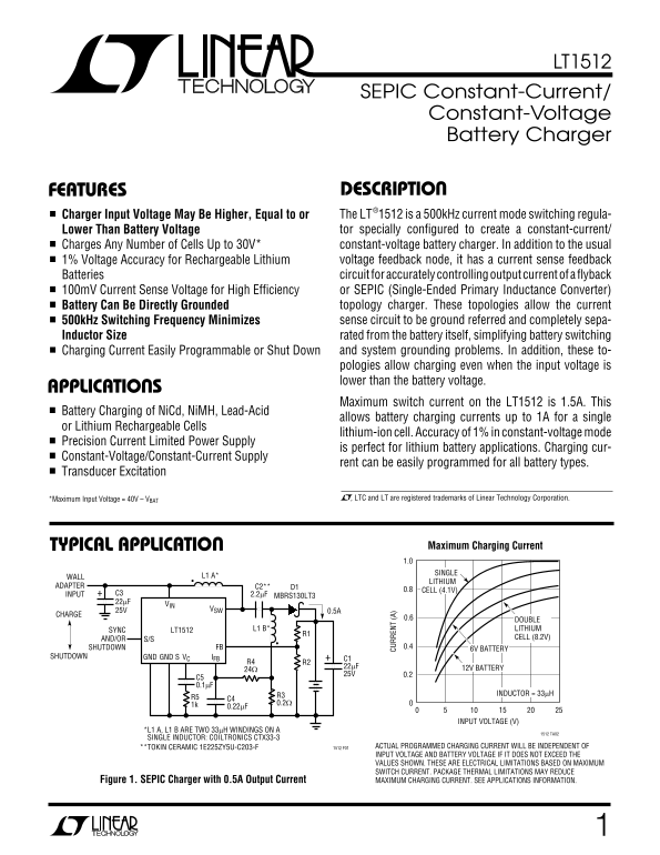
The LT1512 is a high-efficiency, versatile switching regulator designed for sophisticated power management and reliable battery charging solutions. This comprehensive guide covers its application as both a Constant-Current/Constant-Voltage charger (supporting Li-ion, NiCd, NiMH, and Lead-Acid) and an SEPIC converter. It provides detailed circuit topologies and performance specifications, making it ideal for electronics designers building advanced portable systems requiring precision current sensing, high efficiency, or complex voltage regulation across various input conditions.
Page 1 Text Content
LT1512
SEPIC Constant-Current/ Constant-Voltage
Battery Charger
FEATURES DESCRIPTION Charger Input Voltage May Be Higher, Equal to or The LT®1512 is a 500k Hz current mode switching regula- Lower Than Battery Voltage tor specially configured to create a constant-current/
Charges Any Number of Cells Up to 30V* constant-voltage battery charger. In addition to the usual
1% Voltage Accuracy for Rechargeable Lithium voltage feedback node, it has a current sense feedback Batteries circuit for accurately controlling output current of a flyback 100m V Current Sense Voltage for High Efficiency or SEPIC (Single-Ended Primary Inductance Converter) Battery Can Be Directly Grounded topology charger. These topologies allow the current 500k Hz Switching Frequency Minimizes sense circuit to be ground referred and completely sepa- Inductor Size rated from the battery itself, simplifying battery switching Charging Current Easily Programmable or Shut Down and system grounding problems. In addition, these to- pologies allow charging even when the input voltage is lower than the battery voltage.
APPLICATIONS
CU RR EN (A
Maximum switch current on the LT1512 is 1.5A. This
Battery Charging of Ni Cd, Ni MH, Lead-Acid
allows battery charging currents up to 1A for a single
or Lithium Rechargeable Cells
lithium-ion cell. Accuracy of 1% in constant-voltage mode
Precision Current Limited Power Supply
is perfect for lithium battery applications. Charging cur-
Constant-Voltage/Constant-Current Supply
rent can be easily programmed for all battery types.
Transducer Excitation
*Maximum Input Voltage = 40V – VBAT , LTC and LT are registered trademarks of Linear Technology Corporation.
TYPICAL APPLICATION Maximum Charging Current 1.0 SINGLE
WALL L1 A*
LITHIUM
ADAPTER C2** D1
0.8 CELL (4.1V)
INPUT C3 2.2µF
MBRS130LT3
25V VSW
CHARGE
0.6 DOUBLE
SYNC LT1512 L1 B* LITHIUM
AND/OR CELL (8.2V)
SHUTDOWN FB 0.4
6V BATTERY
SHUTDOWN GND GND S IFBVC
22µF 12V BATTERY
R3 INDUCTOR = 33µH
INPUT VOLTAGE (V)
L1 A, L1 B ARE TWO 33µH WINDINGS ON A
1512 TA02
SINGLE INDUCTOR: COILTRONICS CTX33-3
TOKIN CERAMIC 1E225ZY5U-C203-F 1512 F01 ACTUAL PROGRAMMED CHARGING CURRENT WILL BE INDEPENDENT OF INPUT VOLTAGE AND BATTERY VOLTAGE IF IT DOES NOT EXCEED THE VALUES SHOWN. THESE ARE ELECTRICAL LIMITATIONS BASED ON MAXIMUM SWITCH CURRENT. PACKAGE THERMAL LIMITATIONS MAY REDUCE Figure 1. SEPIC Charger with 0.5A Output Current MAXIMUM CHARGING CURRENT. SEE APPLICATIONS INFORMATION.
Page Summary Contents For LINEAR TECHNOLOGY LT1512 User Guide
Manual Details
| Brand | Linear |
|---|---|
| Pages | 12 |
| File Size | 229.69 KB |
| Published | June 01, 2026 |
Enter the captcha to get the download link:

Frequently Asked Questions
What types of batteries can the LT1512 charger handle?
It supports charging of NiCd, NiMH, Lead-Acid, and Lithium rechargeable cells.
What is the maximum switch current on this device?
The maximum switch current on the LT1512 can reach 1.5A.
Does the charger need input voltage higher than the battery voltage to work?
No, these topologies allow charging even when the input voltage is lower than the battery voltage.
Are there operational limitations regarding temperature and power?
Yes; package thermal limitations may reduce the programmed charging current, and the Maximum Input Voltage is 40V.