# A B C D E F G H I J K L M N O P Q R S T U V W X Y Z

LINEAR TECHNOLOGY LT1579 User Guide

Summary

This advanced low-dropout regulator provides reliable 300mA output power with automatic switching between two independent input sources. Featuring critical protection methods, like reverse-battery, current limiting, and status monitoring flags, it guarantees uninterrupted operation for critical systems requiring backup power (e.g., embedded or industrial electronics). This technical guide details the device's operational characteristics, adjustable voltage options, and advanced failure management features, making it essential reading for power system architects and hardware engineers.
📄 Preview PAGE OF 20

Page 1 Text Content

LT1579

INPUT CURRENT (m A)

300m A Dual Input Smart Battery Backup Regulator

FEATURES DESCRIPTION

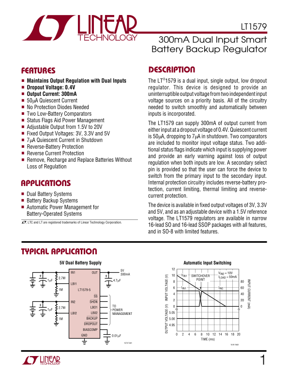
Maintains Output Regulation with Dual Inputs The LT®1579 is a dual input, single output, low dropout Dropout Voltage: 0.4V regulator. This device is designed to provide an Output Current: 300m A uninterruptible output voltage from two independent input 50µA Quiescent Current voltage sources on a priority basis. All of the circuitry

No Protection Diodes Needed needed to switch smoothly and automatically between Two Low-Battery Comparators inputs is incorporated.

Status Flags Aid Power Management

The LT1579 can supply 300m A of output current from

Adjustable Output from 1.5V to 20V

either input at a dropout voltage of 0.4V. Quiescent current

Fixed Output Voltages: 3V, 3.3V and 5V

is 50µA, dropping to 7µA in shutdown. Two comparators

7µA Quiescent Current in Shutdown

are included to monitor input voltage status. Two addi-

Reverse-Battery Protection

tional status flags indicate which input is supplying power

Reverse Current Protection

and provide an early warning against loss of output

Remove, Recharge and Replace Batteries Without

regulation when both inputs are low. A secondary select

Loss of Regulation OU TP UT OL TA GE (V Daisy-Chained Control Outputs IN PU VO LT AG (V

pin is provided so that the user can force the device to switch from the primary input to the secondary input. APPLICATIONS Internal protection circuitry includes reverse-battery pro- tection, current limiting, thermal limiting and reverse-

Dual Battery Systems

current protection.

Battery Backup Systems

The device is available in fixed output voltages of 3V, 3.3V

Automatic Power Management for

and 5V, and as an adjustable device with a 1.5V reference

Battery-Operated Systems

voltage. The LT1579 regulators are available in narrow

, LTC and LT are registered trademarks of Linear Technology Corporation.

16-lead SO and 16-lead SSOP packages with all features, and in SO-8 with limited features.

TYPICAL APPLICATION

5V Dual Battery Supply Automatic Input Switching

IN1 OUT VIN2 = 10V

300m A VIN1

ILOAD = 50m ASWITCHOVER

1µF 4.7µF POINT

IIN1 IIN2

1M LT1579-5

SS IN2 SHDN

2.7M LBO1

1µF POWER

LBI2 LB02 5.05

MANAGEMENT

1M BACKUP 5.00 DROPOUT

BIASCOMP GND 0.01µF

TIME (ms)

1579 TA01

1578 TA02

Page Summary Contents For LINEAR TECHNOLOGY LT1579 User Guide

Page 1 LT1579 INPUT CURRENT (m A) 300m A Dual Input Smart Battery Backup Regulator FEATURES DESCRIPTION Maintains Output Regulation with Dual Inputs The LT®1579 is a dual input, single output, low dropout Dr...
Page 2 LT1579 ABSOLUTE MAXIMUM RATINGS Power Input Pin Voltage ±20V* BIASCOMP Pin Voltage 6.5V, – 0.6V Output Pin Voltage BIASCOMP Pin Current 5m A Fixed Devices............................................. ...
Page 3 LT1579 ELECTRICAL CHARACTERISTICS PARAMETER CONDITIONS MIN TYP MAX UNITS Regulated Output LT1579-3 VIN1 = VIN2 = 3.5V, ILOAD = 1m A, TJ = 25°C 2.950 3.000 3.050 Voltage (Note 1) 4V < VIN1 < 20V,...
Page 4 LT1579 ELECTRICAL CHARACTERISTICS PARAMETER CONDITIONS MIN TYP MAX UNITS Adjust Pin Bias Current TJ = 25°C n A (Notes 2, 7) Minimum Input Voltage ILOAD = 0m A 2.7 3.2 (Note 8) Minimum Load Current LT1...
Page 5 OU TP UT OL TA GE (V QU IE SC EN CU RR EN (µ A) DR OP OU VO LT AG (V LT1579 TYPICAL PERFORMANCE CHARACTERISTICS Guaranteed Dropout Voltage Dropout Voltage Quiescent Current 0.8 0.7 = TEST POINTS A: IL...
Page 6 LT1579 TYPICAL PERFORMANCE CHARACTERISTICS IN PU CU RR EN (m A) IN PU CU RR EN (m A) IN PU CU RR EN (m A) GROUND PIN CURRENT (µA) GROUND PIN CURRENT (m A) GROUND PIN CURRENT (m A) Input and Ground Pin...
Page 7 SE CO ND AR SE LE CT IN UR RE NT (µ A) SH UT DO PI CU RR EN (µ A) GR OU ND IN UR RE NT (m A) LT1579 TYPICAL PERFORMANCE CHARACTERISTICS Ground Pin Current Minimum Input Voltage Shutdown Pin Threshold ...
Page 8 AD JU ST IN IN PU CU RR EN (m A) CO PA RA TO HY ST ER ES IS (m V) LO GI FL AG IN PU CU RR EN (m A) LT1579 TYPICAL PERFORMANCE CHARACTERISTICS Logic Flag Input Current Low-Battery Comparator (Output Hi...
Page 9 RI PP LE EJ EC TI ON (d B) LT1579 TYPICAL PERFORMANCE CHARACTERISTICS OU TP UT OL TA GE LO AD UR RE NT (m A) DE VI AT IO (m V) LT1579-5 “Hot” Plugging and Ripple Rejection Load Regulation Unplugging T...
Page 10 LT1579 PIN FUNCTIONS out of the pin (see curve of Adjust Pin Bias Current vs nally clamped to 7V and –0.6V (one VBE). If unused, this Temperature in the Typical Performance Characteristics). pin can b...
Page 11 LT1579 PIN FUNCTIONS LBO1: This is the open collector output of the low-battery LBO2: This is the open collector output of the low-battery comparator LB1. This output pulls low when the com- comparato...
Page 12 LT1579 APPLICATIONS INFORMATION Device Overview currents and logic functions. In shutdown, quiescent currents are 2µA from the primary input, 2µA from the The LT1579 is a dual input, single output, lo...
Page 13 LT1579 APPLICATIONS INFORMATION A small capacitor placed in parallel with the top resistor BIASCOMP Pin Compensation (R2) of the output divider is necessary for stability and The BIASCOMP pin is a con...
Page 14 LT1579 APPLICATIONS INFORMATION if VIN2 >VIN1, so typically only 3µA. The primary input will Low-Battery Comparators automatically go into standby mode as the primary input There are two independen...
Page 15 LT1579 APPLICATIONS INFORMATION Example: The low-battery detector must be tripped at a current supplied to the load from each input. Normal terminal voltage of 5.5V. There is a 100k pull-up resistor o...
Page 16 LT1579 APPLICATIONS INFORMATION Five milestones are noted on the timing diagram. Time A 1. The output current from each input multiplied by the is where the primary input voltage drops enough to trip ...
Page 17 LT1579 APPLICATIONS INFORMATION resistance from the junction to a ground lead is 40°C/W for Therefore, 16-lead SSOP, 32°C/W for 16-lead SO and 35°C/W for P = (150m A)(7V – 5V) + (2m A)(7V) = 0.31W 8-l...
Page 18 LT1579 APPLICATIONS INFORMATION The inputs of the device can withstand reverse voltages up flow from one input to another will be limited to less than to 20V. Current flow into the device will be limi...
Page 19 LT1579 PACKAGE DESCRIPTION Dimensions in inches (millimeters) unless otherwise noted. S8 Package 8-Lead Plastic Small Outline (Narrow 0.150) (LTC DWG # 05-08-1610) 0°– 8° TYP (0.101 – 0.254) (0.355 – ...
Page 20 LT1579 TYPICAL APPLICATION Additional Logic Forces LT1579 Into Shutdown to Protect Input Batteries IN1 OUT LBI1 BACKUP MAIN GOOD D1 TO D3: 1N4148 R4 LBO1 DROPOUT NC SS IN2 IN2 1µF LT1579-5 D3 R5 LBI2 ...

Manual Details

Brand Linear
Pages 20
File Size 294.70 KB
Published June 03, 2026
52 views

Enter the captcha to get the download link:

captcha

Frequently Asked Questions

What is the maximum output current?

The device can supply 300mA of uninterruptible output voltage.

How does the LT1579 switch between input sources?

It automatically monitors two independent inputs and provides status flags indicating which input is supplying power. You can also manually force a switch using the Loss of Regulation pin.

What kind of protection features are included?

Internal circuitry includes reverse-battery protection, current limiting, thermal limiting, and dual battery systems current protection.

Can I operate this with multiple voltages?

Yes. It is available as an adjustable device (1.5V to 20V) or fixed in 3V, 3.3V, and 5V options.