# A B C D E F G H I J K L M N O P Q R S T U V W X Y Z

LINEAR TECHNOLOGY LT1013 Data SheetLT1014 Specification Manual

Summary

These ultra-high precision operational amplifiers are designed for demanding instrumentation applications requiring superior accuracy and efficiency in environments from battery-powered systems to industrial condition monitoring. The manual details comprehensive specifications, highlighting features like extremely low offset voltage, low noise, and compatibility with single supply designs. It serves as a critical reference guide for electrical engineers and design specialists building high-reliability measurement circuits such as strain gauge signal conditioners and current loop transmitters.
📄 Preview PAGE OF 24

Page 1 Text Content

LT1013/LT1014

Quad Precision Op Amp (LT1014) Dual Precision Op Amp (LT1013) FEATURES DESCRIPTIO ®1014 is the first precision quad operational amplifier

Single Supply Operation The LT Input Voltage Range Extends to Ground which directly upgrades designs in the industry standard Output Swings to Ground while Sinking Current 14-pin DIP LM324/LM348/OP-11/4156 pin configuration. Pin Compatible to 1458 and 324 with Precision Specs It is no longer necessary to compromise specifications, Guaranteed Offset Voltage: 150μV Max while saving board space and cost, as compared to single

Guaranteed Low Drift: 2μV/°C Max operational amplifiers.

Guaranteed Offset Current: 0.8n A Max

The LT1014’s low offset voltage of 50μV, drift of 0.3μV/°C,

Guaranteed High Gain

offset current of 0.15n A, gain of 8 million, common mode

5m A Load Current: 1.5 Million Min

rejection of 117d B and power supply rejection of 120d B

17m A Load Current: 0.8 Million Min

qualify it as four truly precision operational amplifiers.

Guaranteed Low Supply Current: 500μA Max

Particularly important is the low offset voltage, since no

Low Voltage Noise, 0.1Hz to 10Hz: 0.55μVp-p

offset null terminals are provided in the quad configura-

Low Current Noise—Better than 0P-07, 0.07p A/√Hz

tion. Although supply current is only 350μA per amplifier, a new output stage design sources and sinks in excess of APPLICATIO 20m A of load current, while retaining high voltage gain. Similarly, the LT1013 is the first precision dual op amp in

Battery-Powered Precision Instrumentation

NU BE OF NI TS the 8-pin industry standard configuration, upgrading the

Strain Gauge Signal Conditioners

performance of such popular devices as the MC1458/

Thermocouple Amplifiers

1558, LM158 and OP-221. The LT1013’s specifications

Instrumentation Amplifiers

are similar to (even somewhat better than) the LT1014’s.

4m A–20m A Current Loop Transmitters

Multiple Limit Threshold Detection Both the LT1013 and LT1014 can be operated off a single Active Filters 5V power supply: input common mode range includes Multiple Gain Blocks ground; the output can also swing to within a few millivolts of ground. Crossover distortion, so apparent on previous

, LT, LTC and LTM are registered trademarks of Linear Technology Corporation.

All other trademarks are the property of their respective owners. single-supply designs, is eliminated. A full set of specifi- cations is provided with ±15V and single 5V supplies.

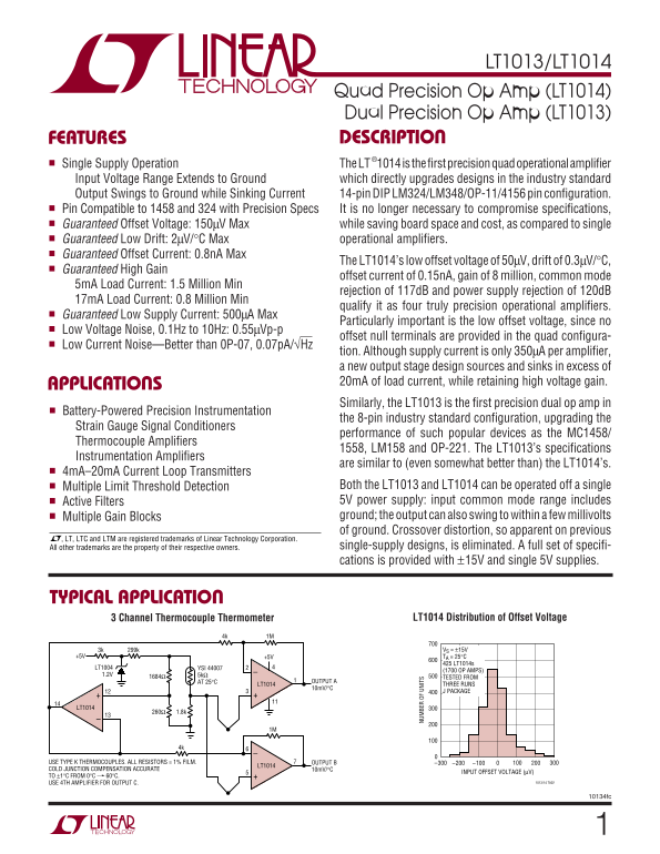
TYPICAL APPLICATIO

LT1014 Distribution of Offset Voltage3 Channel Thermocouple Thermometer

299k3k VS = ±15V +5V+5V TA = 25°C 425 LT1014s

LT1004 YSI 44007

(1700 OP AMPS)

TESTED FROM

AT 25°C OUTPUT A

LT1014 THREE RUNS

J PACKAGE

LT1014

USE TYPE K THERMOCOUPLES. ALL RESISTORS = 1% FILM. OUTPUT B –300 –100 200–200

LT1014

COLD JUNCTION COMPENSATION ACCURATE 10m V/°C

INPUT OFFSET VOLTAGE (μV)

TO ±1°C FROM 0°C 60°C.

USE 4TH AMPLIFIER FOR OUTPUT C. 1013/14 TA02

10134fc

Page Summary Contents For LINEAR TECHNOLOGY LT1013 Data SheetLT1014 Specification Manual

Page 1 LT1013/LT1014 Quad Precision Op Amp (LT1014) Dual Precision Op Amp (LT1013) FEATURES DESCRIPTIO ®1014 is the first precision quad operational amplifier Single Supply Operation The LT Input Voltage Ran...
Page 2 LT1013/LT1014 ABSOLUTE AXI RATI GS (Note 1) Supply Voltage ±22V Lead Temperature (Soldering, 10 sec.) 300°C Differential Input Voltage ±30V Operating Temperature Range Input Voltage Equal to Positive ...
Page 3 LT1013/LT1014 TA = 25°C. VS = ±15V, VCM = 0V unless otherwise noted.ELECTRICAL CHARACTERISTICS LT1013AM/AC LT1013C/D/I/M LT1014AM/AC LT1014C/D/I/M SYMBOL PARAMETER CONDITIONS MIN TYP MAX MIN TYP MAX U...
Page 4 LT1013/LT1014 ELECTRICAL CHARACTERISTICS The ● denotes the specifications which apply over the temperature range –55°C ≤ TA ≤ 125°C. V S = ±15V, VCM = 0V unless otherwise noted. LT1013AM LT1014AM LT10...
Page 5 LT1013/LT1014 ELECTRICAL CHARACTERISTICS The ● denotes the specifications which apply over the temperature range –40°C ≤ TA ≤ 85°C for LT1013I, LT1014I, 0°C ≤ TA ≤ 70°C for LT1013C, LT1013D, LT1014C, ...
Page 6 VO LT AG NO IS DE NS IT (n V/ √H z) CO ON OD RE JE CT IO RA TI (d B) IN PU OF FS ET OL TA GE (μ V) CU RR EN NO IS DE NS IT (f A /√ Hz LT1013/LT1014 TYPICAL PERFOR A CE CHARACTERISTICS Offset Voltage D...
Page 7 SA TU RA TI ON OL TA GE (V ON OD IN PU VO LT AG E, +5 V, (V LT1013/LT1014 TYPICAL PERFOR A CE CHARACTERISTICS Input Bias Current vs Input Offset Current vs Input Bias Current vs Common Mode Voltage Te...
Page 8 SH OR T- CI RC UI CU RR EN (m A) SI NK IN SO UR CI NG LT1013/LT1014 TYPICAL PERFOR A CE CHARACTERISTICS VO LT AG GA IN (d B) Output Short-Circuit Current Voltage Gain vs Load vs Time Resistance Voltag...
Page 9 LT1013/LT1014 APPLICATIO IN PU (m V) S I OU TP UT (V FOR ATIO b) When the input is more than 400m V below ground (at D when A’s output is negative saturation. B’s and C’s 25°C), the input stage satura...
Page 10 LT1013/LT1014 APPLICATIO S I FOR ATIO Low Supply Operation Test Circuit for Offset Voltage and Offset Drift with Temperature The minimum supply voltage for proper operation of the LT1013/LT1014 is 3.4...
Page 11 LT1013/LT1014 TYPICAL APPLICATIO Hot Wire Anemometer Q2–Q5 CA3046 Q1 PIN 3 TO –15V 1μF LT1014 33k LT1014 +15V 12k 0–1000 FEET/MINUTE10M RESPONSE 2M TIME FULL- ADJUST LT1014 ZERO 3.3k #328 SCALE FLOW 1...
Page 12 LT1013/LT1014 TYPICAL APPLICATIO 5V Powered Precision Instrumentation Amplifier INPUT LT1014 CABLE SHIELDS LT1014 –INPUT RG (TYP 2k) LT1014 OUTPUT LT1014 +INPUT 1% FILM RESISTOR. MATCH 10k's 0.05% +5V...
Page 13 LT1013/LT1014 TYPICAL APPLICATIO 5V Powered Motor Speed Controller No Tachometer Required 1/2 LT1013 2N3904 1/4 CD4016 A2 1/2 LT1013 0.47 MOTOR = CANON–FN30–R13N1B. A1 DUTY CYCLE MODULATES MOTOR. A2 S...
Page 14 LT1013/LT1014 TYPICAL APPLICATIO Methane Concentration Detector with Linearized Output +5V 1% METAL FILM RESISTOR SENSOR = CALECTRO-GC ELECTRONICS #J4-807 OR FIGARO #813 LT1004 –5V CD4016 1N4148 (4) L...
Page 15 LT1013/LT1014 TYPICAL APPLICATIO 5V Powered 4m A–20m A Current Loop Transmitter† 2N2222 1/2 LT1013 4k* TRIM 4m A-20m A OUT 4.3k A2 TO LOAD +5V 2.2kΩ MAXIMUM 12-BIT ACCURACY. 1/2 LT1013 1% FILM. T1 = P...
Page 16 LT1013/LT1014 TYPICAL APPLICATIO 5V Powered, Linearized Platinum RTD Signal Conditioner OUTPUT 1/4 LT1014 1/4 LT1014 5k LINEARITY GAIN TRIM 1.5k SENSOR 3.01k ROSEMOUNT 8.25k 118MF A3 1/4 LT1014 50k ZE...
Page 17 LT1013/LT1014 TYPICAL APPLICATIO LVDT Signal Conditioner FREQUENCY = +5V 1.5k Hz LVDTYEL-BLK LT1013 RD- BLUE YEL-RD BLK LT1004 1.2k OUT 1μF LT1013 1/2 LTC1043 100k LT1011 TO PIN 16, LT1043 LVDT = SCHA...
Page 18 LT1013/LT1014 TYPICAL APPLICATIO Low Dropout Regulator for 6V Battery +12 OUTPUT 8LTC1044 5V OUTPUT VBATT 6V 1.2k LT1004 LT1013 1.2V A2 LT1013 0.009V DROPOUT AT 5m A OUTPUT. 0.108V DROPOUT AT 100m A O...
Page 19 LT1013/LT1014 TYPICAL APPLICATIO 6V to ±15V Regulating Converter +V Q1 CLK 2 +15VOUT 100k Hz INPUT CLK 1 Q274C74 0.00510 1.4M L1 D1 Q1 Q2D2 1MHY LT1013 VOUT 10k +6V ADJ 82k LT1004 1.2V LT1013 L1 = 24-...
Page 20 LT1013/LT1014 SCHE ATIC DIAGRA 1/2 LT1013, 1/4 LT1014 OUTPUT IN Q18 1013/14 SD 10134fc
Page 21 LT1013/LT1014 PACKAGE DESCRIPTIO H Package 8-Lead TO-5 Metal Can (.200 Inch PCD) (Reference LTC DWG # 05-08-1320) 45°TYP PIN 1 MAX (1.270) 0.165 – 0.185 MAX (4.191 – 4.699) REFERENCE SEATING PLANE GAU...
Page 22 LT1013/LT1014 PACKAGE DESCRIPTIO N8 Package 8-Lead PDIP (Narrow .300 Inch) (Reference LTC DWG # 05-08-1510) .400* (10.160) MAX .065 (1.651) .008 – .015 TYP +.035 MIN (0.508) .325 –.015 MIN.018 ± .003 ...
Page 23 LT1013/LT1014 PACKAGE DESCRIPTIO S8 Package 8-Lead Plastic Small Outline (Narrow .150 Inch) (Reference LTC DWG # 05-08-1610) .050 BSC MIN (4.801 – 5.004) NOTE 3 .008 – .010 TYP (0.203 – 0.254) 0°– 8° ...
Page 24 LT1013/LT1014 TYPICAL APPLICATIO Step-Up Switching Regulator for 6V Battery OUTPUT INPUT 200k LT1004 1MHY 1.2V 1N5821 LT1013 LT1013 2N5262 LT = AIE–VERNITRON 24–104 78% EFFICIENCY 1013/14 TA23 RELATED...