LINEAR TECHNOLOGY LTC3217 User Guide Specification
Summary
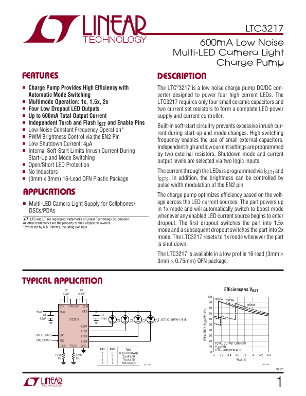
The LTC3217 is a highly efficient, low-noise charge pump DC/DC converter designed to power high-current, multi-LED camera flashes. This manual details advanced features including automatic 1x, 1.5x, and 2x boost modes, independent torch and flash control, and soft-start protection. Ideal for cellphones, DSC cameras, and PDAs requiring a reliable, low-power lighting solution with up to 600mA total output current.
Page 1 Text Content
LTC3217
600m A Low Noise Multi-LED Camera Light Charge Pump
FEATURES DESCRIPTIO Charge Pump Provides High Efficiency with The LTC®3217 is a low noise charge pump DC/DC con- Automatic Mode Switching verter designed to power four high current LEDs. The Multimode Operation: 1x, 1.5x, 2x LTC3217 requires only four small ceramic capacitors and Four Low Dropout LED Outputs two current set resistors to form a complete LED power Up to 600m A Total Output Current supply and current controller. Independent Torch and Flash ISET and Enable Pins
Built-in soft-start circuitry prevents excessive inrush cur-
Low Noise Constant Frequency Operation*
rent during start-up and mode changes. High switching
PWM Brightness Control via the EN2 Pin
frequency enables the use of small external capacitors.
Low Shutdown Current: 4µA
Independent high and low current settings are programmed
Internal Soft-Start Limits Inrush Current During
by two external resistors. Shutdown mode and current
Start-Up and Mode Switching
output levels are selected via two logic inputs.
Open/Short LED Protection
No Inductors The current through the LEDs is programmed via ISET1 and (3mm x 3mm) 16-Lead QFN Plastic Package ISET2. In addition, the brightness can be controlled by pulse width modulation of the EN2 pin.
APPLICATIO S
The charge pump optimizes efficiency based on the volt- age across the LED current sources. The part powers up
Multi-LED Camera Light Supply for Cellphones/ EF FI CI EN CY (P LE D/ PI N)
in 1x mode and will automatically switch to boost mode
DSCs/PDAs
whenever any enabled LED current source begins to enter
, LTC and LT are registered trademarks of Linear Technology Corporation. All other trademarks are the property of their respective owners. dropout. The first dropout switches the part into 1.5x *Protected by U.S. Patents, including 6411531
mode and a subsequent dropout switches the part into 2x mode. The LTC3217 resets to 1x mode whenever the part is shut down. The LTC3217 is available in a low profile 16-lead (3mm × 3mm × 0.75mm) QFN package.
TYPICAL APPLICATIO
C2 C3 Efficiency vs VBAT 2.2µF 2.2µF
VBAT VBAT CPO
LTC3217 AOT-2015HPW-1751B
LED1 LED2
EN1 (TORCH) EN1
EN2 (FLASH) EN2
TOTAL OUTPUT CURRENT
ISET1 ISET2 GND
PLED/PIN
EN1 EN2 ILED
LED = 2015 HPW AOT
0 (SHUTDOWN)
25m A/LED
1% 1% VBAT (V)
75m A/LED 100m A/LED 3217 G09
3217 TA01
Page Summary Contents For LINEAR TECHNOLOGY LTC3217 User Guide Specification
Manual Details
| Brand | Linear |
|---|---|
| Pages | 12 |
| File Size | 179.35 KB |
| Published | June 02, 2026 |
Enter the captcha to get the download link:

Frequently Asked Questions
How can I control the brightness of the LEDs?
Brightness can be controlled using Pulse Width Modulation (PWM) applied via the EN2 pin.
What voltage range does the LTC3217 operate within?
The operating voltage ranges from 2.9V to 4.5V.
Does it include protection features for the LEDs?
Yes, it includes Open/Short LED Protection and features programmable independent high and low current settings (I_SET1 and I_SET2).
How does the device manage its power states?
It monitors the voltage across the LED current sources and automatically switches between 1x, 1.5x, and 2x boost modes while maintaining optimization efficiency.