# A B C D E F G H I J K L M N O P Q R S T U V W X Y Z

LINEAR TECHNOLOGY - 1 LTC4006 Data Sheet Manual

Summary

The LTC4006 is a high-efficiency charger controller designed for robust battery management of 2-, 3-, or 4-cell Lithium-Ion batteries. This technical solution provides complete charging capabilities, featuring programmable current limits, precise voltage accuracy, and built-in safety mechanisms like temperature sensing and deep discharge conditioning. The comprehensive manual details features ideal for engineers designing standalone chargers, portable instruments, and sophisticated battery-backup systems requiring reliable, controlled power delivery under various operating conditions.
📄 Preview PAGE OF 20

Page 1 Text Content

LTC4006

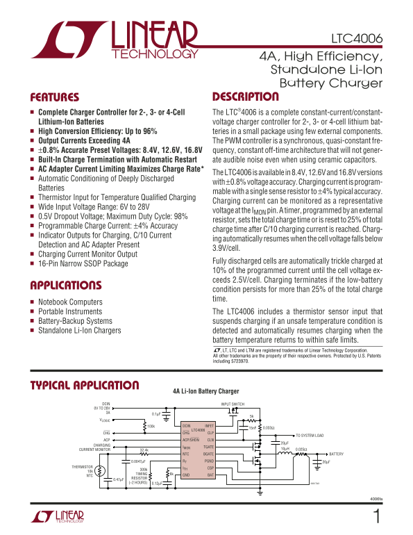
4A, High Efficiency, Standalone Li-Ion Battery Charger FEATURES DESCRIPTIO

Complete Charger Controller for 2-, 3- or 4-Cell The LTC®4006 is a complete constant-current/constant- Lithium-Ion Batteries voltage charger controller for 2-, 3- or 4-cell lithium bat- High Conversion Efficiency: Up to 96% teries in a small package using few external components. Output Currents Exceeding 4A The PWM controller is a synchronous, quasi-constant fre- ±0.8% Accurate Preset Voltages: 8.4V, 12.6V, 16.8V quency, constant off-time architecture that will not gener-

Built-In Charge Termination with Automatic Restart ate audible noise even when using ceramic capacitors.

AC Adapter Current Limiting Maximizes Charge Rate*

The LTC4006 is available in 8.4V, 12.6V and 16.8V versions

Automatic Conditioning of Deeply Discharged

with ±0.8% voltage accuracy. Charging current is program-

Batteries

mable with a single sense resistor to ±4% typical accuracy.

Thermistor Input for Temperature Qualified Charging

Charging current can be monitored as a representative

Wide Input Voltage Range: 6V to 28V

voltage at the IMON pin. A timer, programmed by an external

0.5V Dropout Voltage; Maximum Duty Cycle: 98%

resistor, sets the total charge time or is reset to 25% of total

Programmable Charge Current: ±4% Accuracy

charge time after C/10 charging current is reached. Charg-

Indicator Outputs for Charging, C/10 Current

ing automatically resumes when the cell voltage falls below

Detection and AC Adapter Present

3.9V/cell.

Charging Current Monitor Output

Fully discharged cells are automatically trickle charged at

16-Pin Narrow SSOP Package

10% of the programmed current until the cell voltage ex- ceeds 2.5V/cell. Charging terminates if the low-battery

APPLICATIO

condition persists for more than 25% of the total charge time.

Notebook Computers Portable Instruments The LTC4006 includes a thermistor sensor input that Battery-Backup Systems suspends charging if an unsafe temperature condition is Standalone Li-Ion Chargers detected and automatically resumes charging when the

battery temperature returns to within safe limits. , LT, LTC and LTM are registered trademarks of Linear Technology Corporation. All other trademarks are the property of their respective owners. Protected by U.S. Patents including 5723970.

TYPICAL APPLICATIO

4A Li-Ion Battery Charger

DCIN INPUT SWITCH 0V TO 28V 3A

VLOGIC

100k DCIN INFET

LTC4006

CHG CHG CLP

TO SYSTEM LOAD

ACP ACP/SHDN CLN

CHARGING

IMON TGATE

CURRENT MONITOR 10µH 0.025Ω

NTC BGATE BATTERY

0.0047µF RT PGND 20µF

THERMISTOR ITH CSP

TIMING 6k GND BAT

0.47µF RESISTOR (~2 HOURS) 0.12µF 4006 TA01

4006fa

Page Summary Contents For LINEAR TECHNOLOGY - 1 LTC4006 Data Sheet Manual

Page 1 LTC4006 4A, High Efficiency, Standalone Li-Ion Battery Charger FEATURES DESCRIPTIO Complete Charger Controller for 2-, 3- or 4-Cell The LTC®4006 is a complete constant-current/constant- Lithium-Ion Ba...
Page 2 LTC4006 ABSOLUTE MAXIMUM RATINGS PACKAGE/ORDER INFORMATION (Note 1) Voltage from DCIN, CLP, CLN, TGATE, INFET, TOP VIEW ORDER PART ACP/SHDN, CHG to GND +32V to –0.3V DCIN INFET NUMBER CHG BGATE Voltag...
Page 3 LTC4006 ELECTRICAL CHARACTERISTICS The ● denotes specifications which apply over the full operating temperature range (Note 4), otherwise specifications are at TA = 25°C. VDCIN = 20V, VBAT = 12V unles...
Page 4 LTC4006 ELECTRICAL CHARACTERISTICS The ● denotes specifications which apply over the full operating temperature range (Note 4), otherwise specifications are at TA = 25°C. VDCIN = 20V, VBAT = 12V unles...
Page 5 LTC4006 TYPICAL PERFOR A CE CHARACTERISTICS Disconnect/Reconnect Battery EF Battery Leakage Current vs FI CI EN CY (Load Dump) Battery Voltage VDCIN = 0V 3A STEP 1A STEP 1A STEP VFLOAT 1V/(DIV) 3A STE...
Page 6 LTC4006 PI FU CTIO S RT (Pin 4): Timer Resistor. The timer period is set by CSP (Pin 9): Current Amplifier CA1 Input. This pin and the placing a resistor, RRT, to GND. BAT pin measure the voltage acro...
Page 7 LTC4006 BLOCK DIAGRA VIN 100k DCIN CHG25µA VLOGIC INFET ACP/SHDN RRT TIMER/CONTROLLER OSCILLATOR TBAD 32.4k NTC RESTART THERMISTOR LOBAT BAT3k RSENSE CSP 20µF 1.19V gm = 1m 3k 5.1k CLP gm = 1.5m RCL 1...
Page 8 LTC4006 OPERATIO Overview ACP/SHDN pin. It controls the gate of the input FET to keep a low forward voltage drop when charging and also The LTC4006 is a synchronous current mode PWM step- prevents rev...
Page 9 LTC4006 OPERATIO Table 1. Truth Table for LTC4006 Operation MODE DCIN BAT VOLTAGE BAT CURRENT ACP/SHDN TIMER STATE CHG* Shut Down by Low Adapter Voltage <BAT >UVLO Leakage LOW Reset HIGH Conditi...
Page 10 LTC4006 OPERATIO Table 2. Truth Table for LTC4006 Operation (Supplemental) FROM TO BAT PRESENT C/10 NEXT C/10 MAX BAT TIMER NUMBER STATE STATE MODE DCIN VOLTAGE LATCH LATCH CURRENT ACP/SHDN STATE CHG*...
Page 11 LTC4006 OPERATIO be inhibited if it is not already active. If the charging current LTC4006 decreases below 10% to 15% of programmed current, while engaged in input current limiting, BGATE will be R9 3...
Page 12 LTC4006 APPLICATIO S I FOR ATIO Charger Current Programming Alternatively, a normally closed switch can be used to detect when the battery is present (see Figure 8). The basic formula for charging cur...
Page 13 LTC4006 APPLICATIO S I FOR ATIO Soft-Start BAT BAT )⎛ The LTC4006 is soft started by the 0.12µF capacitor on the ⎝⎜ ⎠⎟ DCIN= ITH pin. On start-up, ITH pin voltage will rise quickly to 0.5V, f RMS then...
Page 14 LTC4006 APPLICATIO S I FOR ATIO Table 4 highest at high input voltages. For VIN < 20V the high MAXIMUM INPUT MINIMUM INDUCTOR current efficiency generally improves with larger MOSFETs, AVERAGE CURR...
Page 15 LTC4006 APPLICATIO S I FOR ATIO Example: between the CLP and DCIN pins. When this voltage ex- ceeds 100m V, the amplifier will override programmed VDCIN = 19V, f OSC = 345k Hz, QG1 = QG2 = 15n C. char...
Page 16 LTC4006 APPLICATIO S I FOR ATIO LTC4006 LTC4006 NTC NTC C7 RTH C7 R9A RTH Figure 10. Voltage Divider Thermistor Network Figure 11. General Thermistor Network you, then simply set R9 = RTH(LOW) RTH = 2...
Page 17 LTC4006 APPLICATIO S I FOR ATIO 100k selection. If the VIN supply is going to collapse very slowly VIN Q1A such that Q1B is not turned on quickly enough for the given load and stay within its PD limit...
Page 18 LTC4006 APPLICATIO S I FOR ATIO 4. Place the output current sense resistor right next to 8. Route analog ground as a trace tied back to IC ground the inductor output but oriented such that the IC’s (a...
Page 19 LTC4006 PACKAGE DESCRIPTION GN Package 16-Lead Plastic SSOP (Narrow .150 Inch) (Reference LTC DWG # 05-08-1641) .009 (0.229) REF .254 MIN .150 – .165 .0015 .0250 BSC.0165 ± RECOMMENDED SOLDER PAD LAYO...
Page 20 LTC4006 TYPICAL APPLICATIO 2A Li-Ion Battery Charger DCIN INPUT SWITCH 0V TO 20V D1: MBRM140T3 Q1, Q2: Si7501DN Q3: Si5435B VLOGIC DCIN INFET C4 RCL LTC4006 15n F 0.04Ω CHG CHG CLP TO SYSTEM LOAD ACP ...

Manual Details

Brand Linear
Pages 20
File Size 261.88 KB
Published June 19, 2026
5 views

Enter the captcha to get the download link:

captcha

Frequently Asked Questions

What number of battery cells does the LTC4006 support?

It is a complete controller for 2-, 3-, or 4-cell lithium batteries.

How does the charger handle extreme temperatures?

The LTC4006 includes a thermistor sensor input, suspending charging if unsafe temperatures are detected.

What is the required input voltage range for operation?

It supports a wide input voltage range: 6V to 28V at the I pin.

How does the device ensure accurate battery termination?

Charging terminates automatically when the cell voltage exceeds 2.5V/cell or if the low-battery condition persists for over 25% of total charge time.