# A B C D E F G H I J K L M N O P Q R S T U V W X Y Z

LINEAR TECHNOLOGY - 1 LTC3736 Data Sheet Manual

Summary

The LTC3736 is a high-efficiency, dual 2-phase synchronous DC/DC step-down controller for demanding portable and battery-powered applications. This revolutionary circuit eliminates the need for external current sense resistors, simplifying design while maximizing performance. The manual details its advanced features, including out-of-phase control for ultra-low dropout operation, wide voltage range (2.75V to 9.8V), constant frequency mode, and adjustable burst mode capability. Ideal for building compact notebooks, PDAs, and portable instruments that require reliable, regulated power delivery.
📄 Preview PAGE OF 28

Page 1 Text Content

LTC3736 TM,

Dual 2-Phase, No RSENSE Synchronous Controller with Output Tracking

FEATURES DESCRIPTIO No Current Sense Resistors Required The LTC®3736 is a 2-phase dual synchronous step-down Out-of-Phase Controllers Reduce Required switching regulator controller with tracking that drives Input Capacitance external complementary power MOSFETs using few exter- Tracking Function nal components. The constant frequency current mode Wide VIN Range: 2.75V to 9.8V architecture with MOSFET VDS sensing eliminates the Constant Frequency Current Mode Operation need for sense resistors and improves efficiency. Power 0.6V ±1.5% Voltage Reference loss and noise due to the ESR of the input capacitance are Low Dropout Operation: 100% Duty Cycle minimized by operating the two controllers out of phase. True PLL for Frequency Locking or Adjustment

Burst Mode operation provides high efficiency at light loads.

Selectable Burst Mode®/Forced Continuous Operation

100% duty cycle capability provides low dropout operation,

Auxiliary Winding Regulation

extending operating time in battery-powered systems.

Internal Soft-Start Circuitry

Power Good Output Voltage Monitor The switching frequency can be programmed up to 750k Hz, Output Overvoltage Protection allowing the use of small surface mount inductors and ca- Micropower Shutdown: IQ = 9µA pacitors. For noise sensitive applications, the LTC3736 Tiny Low Profile (4mm × 4mm) QFN and Narrow switching frequency can be externally synchronized from

SSOP Packages EF FI CI EN CY 250k Hz to 850k Hz. Burst Mode operation is inhibited dur-

ing synchronization or when the SYNC/FCB pin is pulled low APPLICATIO S in order to reduce noise and RF interference. Automatic soft- start is internally controlled.

One or Two Lithium-Ion Powered Devices

The LTC3736 is available in the tiny thermally enhanced

Notebook and Palmtop Computers, PDAs

(4mm × 4mm) QFN package or 24-lead SSOP narrow

Portable Instruments

package.

Distributed DC Power Systems

, LTC and LT are registered trademarks of Linear Technology Corporation. Burst Mode is a registered trademark of Linear Technology Corporation. No RSENSE is a trademark of Linear Technology Corporation. All other trademarks are the property of their respective owners. Protected by U.S. Patents including 5481178, 5929620, 6144194, 6580258, 6304066, 6611131, 6498466.

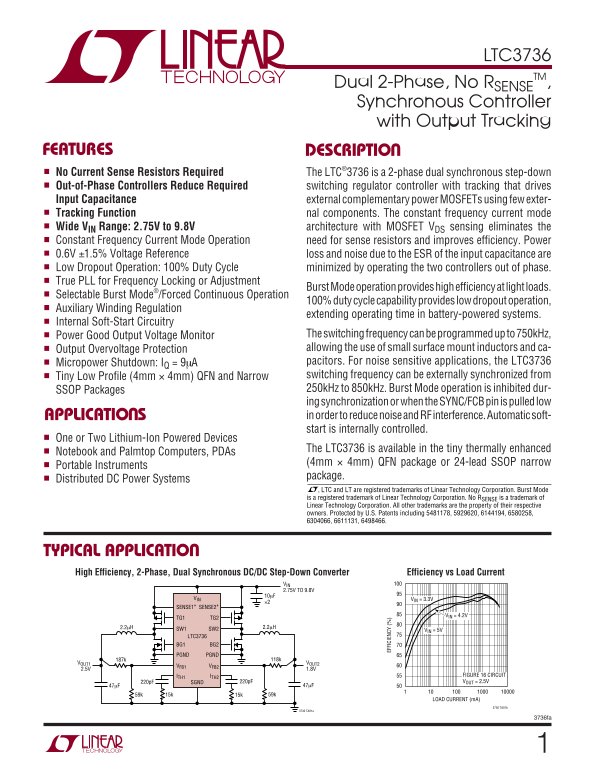
TYPICAL APPLICATIO High Efficiency, 2-Phase, Dual Synchronous DC/DC Step-Down Converter Efficiency vs Load Current

VIN 2.75V TO 9.8V 10µF

VIN VIN = 3.3V

SENSE1+ SENSE2+

VIN = 4.2V

TG1 TG2

2.2µH SW1 SW2 2.2µH

VIN = 5V

LTC3736 BG1 BG2

PGND PGND

VOUT1 VOUT2

VFB1 VFB2

ITH1 ITH2 FIGURE 16 CIRCUIT 220p F SGND 220p F VOUT = 2.5V

LOAD CURRENT (m A)

3736 TA01b

3736 TA01a

3736fa

Page Summary Contents For LINEAR TECHNOLOGY - 1 LTC3736 Data Sheet Manual

Page 1 LTC3736 TM, Dual 2-Phase, No RSENSE Synchronous Controller with Output Tracking FEATURES DESCRIPTIO No Current Sense Resistors Required The LTC®3736 is a 2-phase dual synchronous step-down Out-of-Phas...
Page 2 LTC3736 ABSOLUTE AXI U RATI GS (Note 1) H2 IP RG Input Supply Voltage (VIN) –0.3V to 10V TG1, TG2, BG1, BG2 Peak Output Current (<10µs) 1A PG OO SW PLLLPF, RUN/SS, SYNC/FCB, Operating Temperature R...
Page 3 LTC3736 ELECTRICAL CHARACTERISTICS The ● denotes specifications that apply over the full operating temperature range, otherwise specifications are at TA = 25°C. VIN = 4.2V unless otherwise specified. ...
Page 4 EF FI CI EN CY LTC3736 TYPICAL PERFOR A CE CHARACTERISTICS TA = 25°C unless otherwise noted. Efficiency and Power Loss Load Step vs Load Current Load Step (Burst Mode Operation) (Forced Continuous Mod...
Page 5 RU N/ SS OL TA GE (V CU RR EN LI IT LTC3736 TYPICAL PERFOR A CE CHARACTERISTICS TA = 25°C unless otherwise noted. NR OM AL IZ ED RE QU EN CY Maximum Current Sense Voltage Regulated Feedback Voltage vs...
Page 6 LTC3736 TYPICAL PERFOR A CE CHARACTERISTICS TA = 25°C unless otherwise noted. Shutdown Quiescent Current RUN/SS Start-Up Current SH UT DO CU RR EN (µ A) vs Input Voltage vs Input Voltage RUN/SS = 0V R...
Page 7 LTC3736 PI FU CTIO S (UF/GN Package) For auxiliary winding applications, connect to a resistor SW1/SW2 (Pins 22, 10/Pins 1, 13): Switch Node Connec- divider from the auxiliary output. To synchronize w...
Page 8 LTC3736 FU CTIO AL DIAGRA (Controller 1) SENSE1+ CLK1 MP1 SWITCHING LOGIC ANTISHOOT AND L1 OV1 THROUGH BLANKING VOUT1 SC1 CIRCUIT SENSE1+ BG1 COUT1 SLEEP1 IREV1 SLOPE1 SW1 SENSE1+ IPROG1 VFB1 R1B BURS...
Page 9 LTC3736 FU CTIO AL DIAGRA (Controller 2) SENSE2+ CLK2 MP2 SWITCHING LOGIC ANTISHOOT AND L2 OV2 THROUGH BLANKING VOUT2 SENSE2+ SC2 CIRCUIT COUT2 SLEEP2 IREV2 SLOPE2 SW2 SENSE2+ VFB2 R2B BURSTDIS VOUT1 ...
Page 10 LTC3736 OPERATIO (Refer to Functional Diagram) Main Control Loop rise linearly from approximately 0.65V to 1.3V (being charged by the internal 0.7µA current source), the EAMP The LTC3736 uses a consta...
Page 11 LTC3736 OPERATIO (Refer to Functional Diagram) When a controller is enabled for Burst Mode operation, the (VOUT1 = VFB1 = 0V), then the LTC3736 will try to regulate inductor current is not allowed to ...
Page 12 LTC3736 OPERATIO (Refer to Functional Diagram) Dropout Operation peak sense voltage by a scale factor given by the curve in Figure 1. When the input supply voltage (VIN) decreases towards the output v...
Page 13 LTC3736 OPERATIO (Refer to Functional Diagram) With 2-phase operation, the two controllers of the LTC3736 The reduced input ripple current also means that less are operated 180 degrees out of phase. T...
Page 14 LTC3736 APPLICATIO S I FOR ATIO The typical LTC3736 application circuit is shown in Fig- A reasonable starting point is setting ripple current IRIPPLE ure 13. External component selection for each of ...
Page 15 LTC3736 OR AL IZ ED RE SI ST AN CE APPLICATIO S I FOR ATIO MOSFET manufacturers, and in the variations in QG and t D(OFF) with gate drive (VIN) voltage, the P-channel MOSFET ultimately should be evalu...
Page 16 LTC3736 APPLICATIO S I FOR ATIO operation improves efficiency by reducing MOSFET switch- ∆1 SENSE MAX ing losses, both gate charge loss and transition loss. •= RBURST DS ON However, lower frequency op...
Page 17 LTC3736 APPLICATIO S I FOR ATIO than ferrite. A reasonable compromise from the same This formula has a maximum at VIN = 2VOUT, where IRMS manufacturer is Kool Mµ. Toroids are very space efficient, = I...
Page 18 LTC3736 APPLICATIO S I FOR ATIO 3.3V OR 5V RUN/SS RUN/SS where f is the operating frequency, COUT is the output capacitance and IRIPPLE is the ripple current in the induc- D1 tor. The output ripple is...
Page 19 LTC3736 APPLICATIO S I FOR ATIO OU TP UT OL TA GE VOUT1 VOUT1 VOUT2 VOUT2 TIME TIME (7b) Coincident Tracking (7c) Ratiometric Tracking Figures 7b and 7c. Two Different Modes of Output Voltage Tracking...
Page 20 LTC3736 APPLICATIO S I FOR ATIO PLLLPF SYNC/ FCB DIGITAL EXTERNAL PHASE/ OSCILLATOR FREQUENCY OSCILLATOR DETECTOR Figure 9. Phase-Locked Loop Block Diagram If the external clock frequency is greater t...
Page 21 LTC3736 APPLICATIO S I FOR ATIO VAUX DFB1 VIN +1/2 LTC3736 VFBITH LTC3736 L1 1:N R1 DFB2 R6 TG SYNC/FCB BG COUT Figure 11. Foldback Current Limiting Figure 10. Auxiliary Output Loop Connection If VAUX...
Page 22 LTC3736 APPLICATIO S I FOR ATIO continuous mode is selected and the duty cycle falls below Other losses, including CIN and COUT ESR dissipative the minimum on-time requirement, the output will be regu...
Page 23 LTC3736 APPLICATIO S I FOR ATIO deliver enough current to prevent this problem if the load possible and isolated as much as possible from the power switch resistance is low and it is driven quickly. T...
Page 24 LTC3736 APPLICATIO S I FOR ATIO L1MP1 VOUT1 COUT1MN1 RL1 L2MP2 VOUT2 MN2 COUT2 RL2BOLD LINES INDICATE HIGH, SWITCHING CURRENT LINES. KEEP LINES TO A MINIMUM LENGTH Figure 14. Branch Current Waveforms ...
Page 25 LTC3736 TYPICAL APPLICATIO S RFB1A RFB1B 59k 187k CITH1A 1.5µH VOUT1 Si3447BDV SW1 SENSE1+ 2.5V IPRG1 PGND 2A VFB1 BG1 COUT1 Si3460DV ITH1 SYNC/FCB 22µF RITH1 ×2 IPRG2 TG1 22k CITH1 PLLLPF PGND SGND T...
Page 26 LTC3736 TYPICAL APPLICATIO 2-Phase, 550k Hz, Dual Output Synchronous DC/DC Converter with Different Power Stage Input Supplies RFB1A RFB1B 59k 187k CITH1A 1.5µH VOUT1 SW1 SENSE1+ 2.5V IPRG1 PGND 5A VF...
Page 27 LTC3736 PACKAGE DESCRIPTIO UF Package 24-Lead Plastic QFN (4mm × 4mm) (Reference LTC DWG # 05-08-1697) BOTTOM VIEW—EXPOSED PAD 0.23 TYP 0.75 ± 0.05 R = 0.115 (4 SIDES) (4 SIDES) 0.70 ±0.05 PIN 1 TOP M...
Page 28 LTC3736 TYPICAL APPLICATIO 2-Phase, Single Output Synchronous DC/DC Converter (3.3VIN to 1.8VOUT at 8A) RFB1A RFB1B 59k 118k CITH1A MP1 1.5µH VOUT SW1 SENSE1+ 1.8V IPRG1 PGND 8A VFB1 BG1 Si7540DP COUT...

Manual Details

Brand Linear
Pages 28
File Size 432.20 KB
Published June 18, 2026
7 views

Enter the captcha to get the download link:

captcha

Frequently Asked Questions

What is the input voltage range for this device?

The LTC3736 operates on a wide V Range: 2.75V to 9.8V.

Can I program the switching frequency on the LTC3736?

Yes, the switching frequency can be programmed up to 750kHz and externally synchronized from 250kHz to 850kHz.

How does Burst Mode operation work in this device?

Burst Mode provides high efficiency at light loads and is also used for low dropout operation due to selectable burst or forced continuous modes.

What kind of packages are available for the LTC3736?

It is available in 4mm x 4mm QFN, 24-lead SSOP narrow, and a tiny thermally enhanced package for portable instruments.