LINEAR TECHNOLOGY - 1 LTC1623 Data Sheet Manual
Summary
This dual high-side switch controller manages two N-channel MOSFETs via a single SMBus or I²C interface, enabling precise power plane management in complex electronics. Featuring ultra-low standby current and programmable addressing up to sixteen switches, it is ideal for building portable, industrial, and handheld equipment. The manual provides comprehensive electrical specifications, application insights, and control logic necessary for engineers designing sophisticated power switching systems requiring reliability and efficiency across various voltage levels.
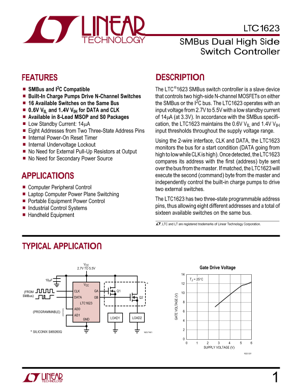
Page 1 Text Content
LTC1623
SMBus Dual High Side Switch Controller
FEATURES DESCRIPTION
SMBus and I2C Compatible The LTC®1623 SMBus switch controller is a slave device Built-In Charge Pumps Drive N-Channel Switches that controls two high-side N-channel MOSFETs on either 16 Available Switches on the Same Bus the SMBus or the I2C bus. The LTC1623 operates with an 0.6V VIL and 1.4V VIH for DATA and CLK input voltage from 2.7V to 5.5V with a low standby current Available in 8-Lead MSOP and S0 Packages of 14µA (at 3.3V). In accordance with the SMBus specifi- Low Standby Current: 14µA cation, the LTC1623 maintains the 0.6V VIL and 1.4V VIH Eight Addresses from Two Three-State Address Pins input thresholds throughout the supply voltage range. Internal Power-On Reset Timer
Using the 2-wire interface, CLK and DATA, the LTC1623
Internal Undervoltage Lockout
monitors the bus for a start condition (DATA going from
No Need for External Pull-Up Resistors at Output
high to low while CLK is high). Once detected, the LTC1623
No Need for Secondary Power Source
compares its address with the first (address) byte sent over the bus from the master. If matched, the LTC1623 will APPLICATIONS GA TE OL TA GE (V execute the second (command) byte from the master and independently control the built-in charge pumps to drive
Computer Peripheral Control
two external switches.
Laptop Computer Power Plane Switching
The LTC1623 has two three-state programmable address
Portable Equipment Power Control
pins, thus allowing eight different addresses and a total of
Industrial Control Systems
sixteen available switches on the same bus.
Handheld Equipment
, LTC and LT are registered trademarks of Linear Technology Corporation.
TYPICAL APPLICATION
2.7V TO 5.5V Gate Drive Voltage
10µF TJ = 25°C
(FROM CLK GA Q1
SMBus)
DATA GB Q2 LTC1623 AD0
(PROGRAMMABLE)
LOAD2LOAD1
* SILICONIX Si69260Q 1623 TA01
SUPPLY VOLTAGE (V)
Page Summary Contents For LINEAR TECHNOLOGY - 1 LTC1623 Data Sheet Manual
Manual Details
| Brand | Linear |
|---|---|
| Pages | 12 |
| File Size | 113.60 KB |
| Published | June 20, 2026 |
Enter the captcha to get the download link:

Frequently Asked Questions
How many switches can the LTC1623 address on one bus?
It supports sixteen available switches using two three-state programmable address pins.
What is the low standby current when operating at 3.3V?
The device maintains 0.6V and 1.4V with a low standby current of 14µA, in accordance with the SMBus specification.
Are external pull-up resistors needed for signal stability?
No, external pull-up resistors are not required at the output when transitioning from high to low while CLK is high.
What happens if the supply voltage drops too low?
The internal Undervoltage Lockout monitors the bus and prevents operation if voltages fall below set thresholds.