LINEAR LT8415 User Manual
Summary
The LT8415 is a highly efficient, low-power boost regulator featuring an integrated dual half-bridge driver optimized for driving MEMS sensors and Piezo Actuators. It boosts input voltages from 2.6V–5V up to 34V while minimizing system board space and power consumption. This compact solution is ideal for engineers developing advanced applications in the medical, military, industrial, and consumer markets that require precise, regulated high voltage for micro-electro-mechanical devices.
Page 1 Text Content
DESIGN IDEAS L
Low Power Boost Regulator with Dual Half-Bridge in 3mm × 2mm DFN Drives MEMS and Piezo Actuators
by Jesus Rosales
Introduction
Advances in manufacturing technol- making it an ideal match for driving 2.6V–5V Input to 34V Output ogy have made it possible for actuators, low current MEMS. MEMS Driver
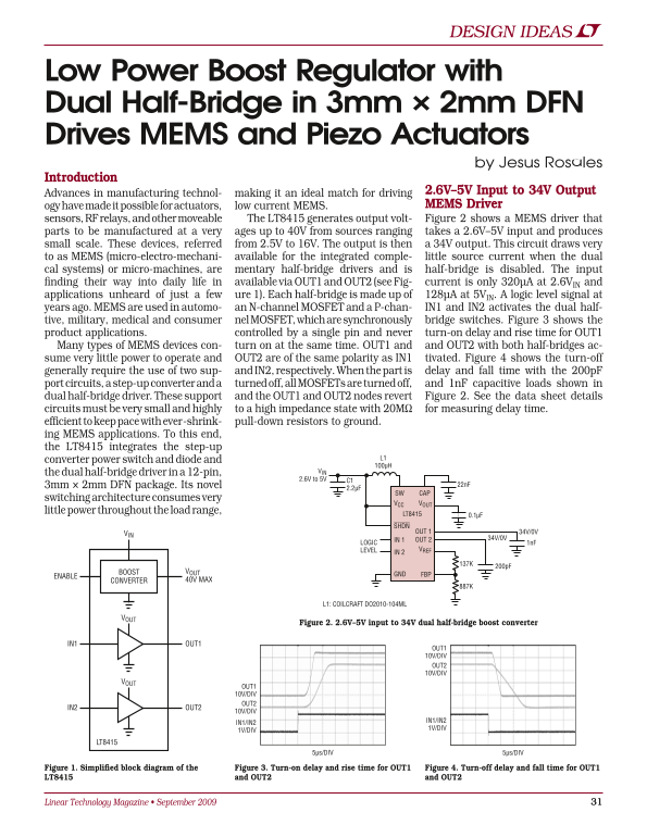
sensors, RF relays, and other moveable The LT8415 generates output volt- Figure 2 shows a MEMS driver that parts to be manufactured at a very ages up to 40V from sources ranging takes a 2.6V–5V input and produces small scale. These devices, referred from 2.5V to 16V. The output is then a 34V output. This circuit draws very to as MEMS (micro-electro-mechani- available for the integrated comple- little source current when the dual cal systems) or micro-machines, are mentary half-bridge drivers and is half-bridge is disabled. The input finding their way into daily life in available via OUT1 and OUT2 (see Fig- current is only 320µA at 2.6VIN and applications unheard of just a few ure 1). Each half-bridge is made up of 128µA at 5VIN. A logic level signal at years ago. MEMS are used in automo- an N-channel MOSFET and a P-chan- IN1 and IN2 activates the dual half- tive, military, medical and consumer nel MOSFET, which are synchronously bridge switches. Figure 3 shows the product applications. controlled by a single pin and never turn-on delay and rise time for OUT1 Many types of MEMS devices con- turn on at the same time. OUT1 and and OUT2 with both half-bridges ac- sume very little power to operate and OUT2 are of the same polarity as IN1 tivated. Figure 4 shows the turn-off generally require the use of two sup- and IN2, respectively. When the part is delay and fall time with the 200p F port circuits, a step-up converter and a turned off, all MOSFETs are turned off, and 1n F capacitive loads shown in dual half-bridge driver. These support and the OUT1 and OUT2 nodes revert Figure 2. See the data sheet details circuits must be very small and highly to a high impedance state with 20MΩ for measuring delay time. efficient to keep pace with ever-shrink- pull-down resistors to ground. ing MEMS applications. To this end, the LT8415 integrates the step-up
converter power switch and diode and
the dual half-bridge driver in a 12-pin, VIN 2.6V to 5V C1
3mm × 2mm DFN package. Its novel 22n F
SW CAP
switching architecture consumes very
VCC VOUT
little power throughout the load range,
LT8415 0.1µF SHDN OUT 1 34V/0V
IN 1 OUT 2 34V/0V
LOGIC 1n F
LEVEL VREF IN 2
BOOST VOUT
GND FBP
ENABLE
CONVERTER 40V MAX
L1: COILCRAFT DO2010-104ML
Figure 2. 2.6V–5V input to 34V dual half-bridge boost converter
IN1 OUT1
OUT1 10V/DIV OUT2 10V/DIV
OUT1 10V/DIV OUT2
IN2 OUT2
10V/DIV
IN1/IN2
IN1/IN2
1V/DIV
1V/DIV
LT8415
5µs/DIV 5µs/DIV
Figure 1. Simplified block diagram of the Figure 3. Turn-on delay and rise time for OUT1 Figure 4. Turn-off delay and fall time for OUT1 LT8415 and OUT2 and OUT2
Linear Technology Magazine • September 2009
Page Summary Contents For LINEAR LT8415 User Manual
Manual Details
| Brand | Linear |
|---|---|
| Pages | 2 |
| File Size | 498.83 KB |
| Published | June 18, 2026 |
Enter the captcha to get the download link:

Frequently Asked Questions
What is the primary application of the LT8415 regulator?
It is ideal for driving low-power MEMS devices and other micro-machines.
What are the input voltage requirements for the LT8415?
The device accepts an input voltage ranging from 2.6V to 5V.
Does the LT8415 support dual half-bridge output?
Yes, it features two distinct outputs, OUT1 and OUT2, each with its own half-bridge driver.
How does the LT8415 maintain minimal power consumption?
It uses a novel switching architecture that consumes very little power across its entire load range.