LINEAR LTC3587 User Guide Manual
Summary
This highly integrated current regulator provides a reliable triple-output supply solution with up to ±32V rails in a tiny 3mm x 3mm package. Designed for space-constrained systems, it features high efficiency and intelligent soft-start sequencing, minimizing external components. Ideal for engineers developing demanding battery-powered devices such as digital cameras, portable scanners, video displays, or handheld medical equipment that require multiple coordinated high voltage supplies.
Page 1 Text Content
L DESIGN FEATURES
±32V Triple-Output Supply for LCDs, CCDs and LEDs Includes Fault Protection in a 3mm × 3mm QFN
by Eko T. Lisuwandi
Introduction The task of designing a battery pow- component count produces a small, the switches are disabled. The LT3587 ered system with multiple high voltage efficient solution. Typical applications also includes a bidirectional fault pin supplies is a daunting one. In such include digital still and video cameras, (FLT), which can be used for fault systems board space is at a premium high performance portable scanners indication (output) or for emergency and high efficiency is required to and display systems, PDAs, cellular shutdown (input). extend battery life. Supplies must be phones and handheld computers that The LT3587 offers a wide output sequenced in start-up and shut-down, have high voltage peripherals such as range, up to 32V for the positive chan- and multiple supplies must be able to CCD sensors, LED backlights, LCD nels (channels 1 and 3) and –32V for maintain regulation without interac- displays or OLED displays. the inverter (channel 2). Channel 3 tion across supplies. is configurable as either a voltage or
The LT3587 is a 1-chip solution Features current regulator. When configured as
that combines three switching regu- To keep the component count low, the a current regulator, channel 3 uses a lators and three internal high voltage LT3587 integrates three high voltage 1-wire output that requires no current switches to produce two high voltage power switches capable of switching sense or high current ground return boost converters and a single high volt- 0.5A, 1A and 1.1A at up to 32V in lines, easing board layout. A single age inverter. The LT3587 is designed to a 3mm × 3mm QFN package. Each resistor programs each of the three run from inputs ranging from 2.5V to of the positive channels includes an channels output voltage levels and/or 6V, making it ideal for battery powered output disconnect to prevent a direct the channel 3 output current level. systems. Small package size and low DC path from input to output when Intelligent soft-start allows for
sequential soft-start of channel 1 fol- lowed by the inverter negative output
LED DRIVER
20m A UP TO 24V using a single capacitor. Internal sequencing circuitry disables the RVFB3 inverter until channel 1 output has
C4 VVIN
2.2µF 2.5V TO 6V reached 87% of its final value.
(OPTIONAL) L4 L1
DS3 C6
Triple-Output Supply for CCD
VFB3 VOUT3 CAP3 SW3 VIN SW1 Imager and LED Backlight
DS1RIFB3 C1 10µF
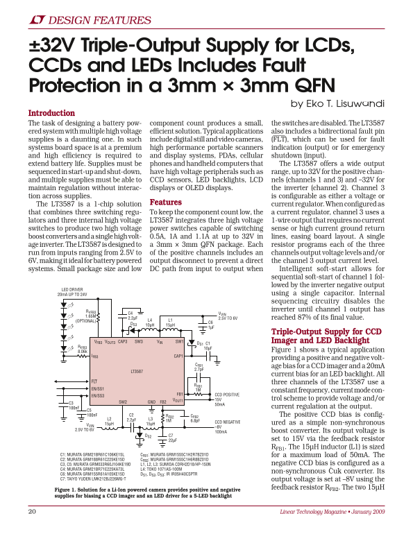
8.06k Figure 1 shows a typical application
IFB3 CAP1
providing a positive and negative volt-
age bias for a CCD imager and a 20m A
LT3587
current bias for an LED backlight. All
FLT three channels of the LT3587 use a
EN/SS1 1M
constant frequency, current mode con-
FB1 CCD POSITIVE
EN/SS3
VOUT1 15V trol scheme to provide voltage and/or
C3 SW2 GND FB2
100n F current regulation at the output.
100n F C2 RFB2 CFB2 The positive CCD bias is config-
2.2µFL2 L3
CCD NEGATIVE ured as a simple non-synchronous
VVIN 15µH 15µH
2.5V TO 6V
100m A boost converter. Its output voltage is
DS2 C7
22µF set to 15V via the feedback resistor RFB1. The 15µH inductor (L1) is sized
C1: MURATA GRM21BR61C106KE15L CFB1: MURATA GRM1555C1H2R7BZ01D for a maximum load of 50m A. The C2: MURATA GRM188R61C225KE15D CFB2: MURATA GRM1555C1H6R8BZ01D
C3, C5: MURATA GRM033R60J104KE19D L1, L2, L3: SUMIDA CDRH2D18/HP-150N negative CCD bias is configured as a
C4: MURATA GRM21BR71E225KA73L L4: TOKO 1071AS-100M
non-synchronous Ćuk converter. Its
C6: MURATA GRM155R61A105KE15D DS1, DS2, DS3: IR IR05H40CSPTR C7: TAIYO YUDEN LMK212BJ226MG-T output voltage is set at –8V using the
feedback resistor RFB2. The two 15µH Figure 1. Solution for a Li-Ion powered camera provides positive and negative
supplies for biasing a CCD imager and an LED driver for a 5-LED backlight
Linear Technology Magazine • January 2009
Page Summary Contents For LINEAR LTC3587 User Guide Manual
Manual Details
| Brand | Linear |
|---|---|
| Pages | 6 |
| File Size | 1.88 MB |
| Published | June 16, 2026 |
Enter the captcha to get the download link:

Frequently Asked Questions
What is the input voltage range of the LT3587?
The LT3587 runs from inputs ranging from 2.5V to 6V.
What is the maximum positive output voltage of the LT3587?
The positive channels (1 and 3) support up to 32V output.
When does the LT3587's inverter channel start up?
The inverter starts once channel 1 output reaches 87% of its final value.
What package does the LT3587 come in?
It is available in a 3mm × 3mm QFN package.