LINEAR LTM4613 User Guide & Manual
Summary
The LTM4613 delivers an ultra-low-EMI, high-performance step-down regulator module engineered for modern IT and communications systems. Designed to overcome complex EMI compliance issues inherent in power-hungry converters, this certified solution meets stringent international standards like EN55022 Class B. It allows designers to achieve guaranteed electromagnetic compatibility and high efficiency (up to 96W) within a compact 15mm x 15mm footprint, simplifying the challenging design process for reliable products.
Page 1 Text Content
Ultralow-EMI, 96W, Step-Down µModule Regulator— EN55022 Class B Certified in a 15mm x 15mm Footprint Richard Ying and Willie Chan
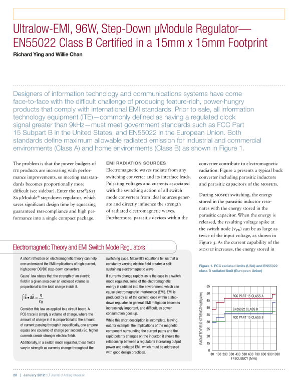
Designers of information technology and communications systems have come face-to-face with the difficult challenge of producing feature-rich, power-hungry products that comply with international EMI standards. Prior to sale, all information technology equipment (ITE)—commonly defined as having a regulated clock signal greater than 9k Hz—must meet government standards such as FCC Part 15 Subpart B in the United States, and EN55022 in the European Union. Both standards define maximum allowable radiated emission for industrial and commercial environments (Class A) and home environments (Class B) as shown in Figure 1.
The problem is that the power budgets of EMI RADIATION SOURCES converter contribute to electromagnetic ITE products are increasing with perfor- Electromagnetic waves radiate from any radiation. Figure 2 presents a typical buck mance improvements, so meeting EMI stan- switching converter and its interface leads. converter including parasitic inductors dards becomes proportionally more Pulsating voltages and currents associated and parasitic capacitors of the MOSFETs. difficult (see sidebar). Enter the LTM®4613 with the switching action of all switch
During MOSFET switching, the energy
8A µModule® step-down regulator, which mode converters from ideal sources gener-
RA DI AT ED IE LD TR EN GT (d Bµ V/
stored in the parasitic inductor reso-
saves significant design time by squeezing ate and directly influence the strength
nates with the energy stored in the
guaranteed EMI-compliance and high per- of radiated electromagnetic waves.
parasitic capacitor. When the energy is
formance into a single compact package. Furthermore, parasitic devices within the
released, the resulting voltage spike at the switch node (VSW) can be as large as twice of the input voltage, as shown in Figure 3. As the current capability of the
Electromagnetic Theory and EMI Switch Mode Regulators MOSFET increases, the energy stored in A short reflection on electromagnetic theory can help switching cycle. Maxwell’s equations tell us that a one understand the EMI implications of high current, constantly varying electric field creates a self-
Figure 1. FCC radiated limits (USA) and EN55022
high power DC/DC step-down converters. sustaining electromagnetic wave.
class B radiated limit (European Union)
Gauss’ law states that the strength of an electric If currents change rapidly, as is the case in a switch field in a given area over an enclosed volume is mode regulator, some of the electromagnetic proportional to the total charge inside it. energy is radiated into the environment, which can
cause electromagnetic interference (EMI). EMI is
q• FCC PART 15 CLASS A
d A =∫ produced by all of the current loops within a step-
down regulator. In general, EMI mitigation becomes Consider this law as applied to a circuit board. A increasingly important, and difficult, as power
EN55022 CLASS B
PCB trace is simply a volume of charge, where the consumption goes up.
FCC PART 15 CLASS B
amount of charge in it is proportional to the amount While this short description is incomplete, leaving of current passing through it (specifically, one ampere out, for example, the implications of the magnetic equals one coulomb of charge per second.) So, higher component surrounding the current paths and the currents create stronger electric fields. rapid polarity changes on the inductor, it shows the
Additionally, in a switch mode regulator, these fields relationship between a regulator’s increasing output vary in strength as currents change throughout the power and radiated EMI, which must be addressed with good design practices.
FREQUENCY (MHz)
20 | January 2012 : LT Journal of Analog Innovation
Page Summary Contents For LINEAR LTM4613 User Guide & Manual
Manual Details
| Brand | Linear |
|---|---|
| Pages | 3 |
| File Size | 2.04 MB |
| Published | June 01, 2026 |
Enter the captcha to get the download link:
