LINEAR LT1500 LT1501 Adaptive-Frequency Current Mode Switching Regulators Data Sheet User Manual
Summary
This manual provides comprehensive documentation for ultra-low quiescent current switching regulators designed for maximizing battery life in portable instrumentation and electronics. Featuring adaptive frequency control, these DC/DC converters deliver reliable power while minimizing noise and standby drain down to microampere levels. Essential reading for engineers designing high-efficiency, compact systems that require stable, low-noise output across varying voltages, especially those utilizing primary or secondary batteries.
Page 1 Text Content
查询LT1500供应商
LT1500/LT1501
Adaptive-Frequency
Current Mode Switching Regulators
FEATURES DESCRIPTION
Low Noise Adaptive-Frequency Current Mode The LT®1500 is an adaptive-frequency current mode step- Operation Avoids Low Frequency Noise at up switching regulator with an internal power switch that Most Load Currents is rated up to 700m A. In contrast to pulse skipping Can Be Externally Synchronized (LT1500) switching regulators, the LT1500 uses a current mode Micropower Quiescent Current: 200µA topology that provides lower noise operation and im- Shutdown Current: 8µA Typ proved efficiency. Only at very light loads is Burst Mode TM Internal Loop Compensation activated to give high efficiency and micropower opera- Low-Battery Comparator Active in Shutdown tion. High switching frequency (up to 500k Hz) allows very Minimum Input Voltage: 1.8V Typ small inductors to be used, along with ceramic capacitors Additional Negative Voltage Feedback Pin (LT1500) if desired. Up to 500k Hz Switching Frequency
The LT1500 operates with input voltages from 1.8V to 15V
Uses Low Profile, Low Cost Surface Mount Inductors
and has only 200µA operating current dropping to 8µA in shutdown. A low-battery comparator is included which stays alive in shutdown. A second output feedback pin
APPLICATIONS
with negative polarity allows negative output voltages to Portable Instrumentation be regulated when the switcher is connected up as a Cuk Battery Operated Systems or a flyback converter.
PDA’s
Two package types are available. The LT1500 comes in a
Standby Power
14-pin SO package, with two options available for fixed output (3.3V or 5V) or adjustable operation. A reduced feature part, the LT1501, comes in the smaller 8-pin SO package with internal frequency compensation. It is also available in adjustable and fixed output voltage versions. , LTC and LT are registered trademarks of Linear Technology Corporation. Burst Mode is a trademark of Linear Technology Corporation.
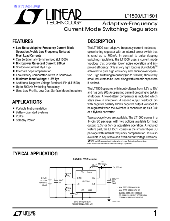
TYPICAL APPLICATION
2-Cell to 5V Converter
D1 MBR0520L
VIN ISENSE
2 EACH SHDN SW
Ni Cd OR 33µF*
LT1501-5 10V
ALKALINE 6V
LBI OUT
CELLS
AVX, TPSC107M006R0150
1% LBO GND AVX, TPSD107M010 R0100
SUMIDA CD73-220, CD54-220
OR CD43-220. SELECT ACCORDING TO MAXIMUM LOAD CURRENT LT1500/01 • TA01
LOW-BATTERY FLAG (USE EXTERNAL PULL-UP)
Page Summary Contents For LINEAR LT1500 LT1501 Adaptive-Frequency Current Mode Switching Regulators Data Sheet User Manual
Manual Details
| Brand | Current |
|---|---|
| Pages | 16 |
| File Size | 194.99 KB |
| Published | May 18, 2026 |
Enter the captcha to get the download link:

Frequently Asked Questions
What is the minimum input voltage for the LT1500 regulator?
The LT1500 operates with input voltages ranging from 1.8V to 15V.
How does the operational current of the LT1500 compare during light loads (shutdown)?
It has a low quiescent current of 200μA, dropping significantly down to just 8μA in shutdown mode.
What physical package options are available for the LT1500 and LT1501?
The LT1500 is available in a 14-pin SO package, while the smaller LT1501 option uses an 8-pin SO package.
Can the regulator output negative voltages?
Yes, it supports regulated negative output voltages when configured as a Cuk converter or flyback converter.