LINEAR Current Sense Amplifier Inputs: -0.3V to 44V Independent of Supply Design Note 451 Data Manual User Guide
Summary
The LT6105 is a precision current sense amplifier designed for monitoring electrical currents in various demanding applications, including solenoids, inductive loads, and power supplies. This comprehensive manual provides detailed operational guidelines and schematics for integrating the device into electromechanical systems. It covers advanced topics such as measuring quarter or half-bridge currents, diagnosing system failures, increasing efficiency, and monitoring both positive and negative voltage rails. Ideal for engineers and technicians developing robust circuit designs requiring accurate, wide-range current monitoring.
Page 1 Text Content
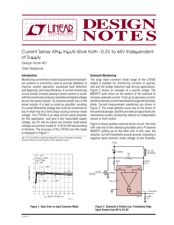
Current Sense Amp Inputs Work from –0.3V to 44V Independent of Supply Design Note 451 Glen Brisebois Introduction Solenoid Monitoring Monitoring current fl ow in electrical and electromechani- The large input common mode range of the LT6105 cal systems is commonly used to provide feedback to makes it suitable for monitoring currents in quarter, improve system operation, accelerate fault detection half and full bridge inductive load driving applications. and diagnosis, and raise effi ciency. A current monitoring Figure 2 shows an example of a quarter bridge. The circuit usually involves placing a sense resistor in series MOSFET pulls down on the bottom of the solenoid to with the monitored conductor and determining the voltage increase solenoid current. It lets go to decrease current, across the sense resistor. To minimize power loss in the and the solenoid current freewheels through the Schottky sense resistor it is kept as small as possible, resulting diode. Current measurement waveforms are shown in in a small differential voltage that must be monitored on Figure 3. The small glitches occur due to the action of top of what may be a fairly large varying common mode the solenoid plunger, and this provides an opportunity for voltage. The LT®6105 is an ideal current sense amplifi er mechanical system monitoring without an independent for this application. Just give it any reasonable supply sensor or limit switch. voltage, say 3V, and its inputs can monitor small sense
Figure 4 shows another solenoid driver circuit, this time
voltages at common modes of –0.3V to 44V and anything
with one end of the solenoid grounded and a P-channel
in between. The accuracy of the LT6105 over this range
MOSFET pulling up on the other end. In this case, the
is displayed in Figure 1.
inductor current freewheels around ground, imposing a
L, LT, LTC and LTM are registered trademarks of Linear Technology Corporation.
negative input common mode voltage of one Schottky
All other trademarks are the property of their respective owners.
24VDC
1Ω SOLENOID
VSENSE = 50m V RIN = 100Ω
AV = 50V
TA = –40°C LT6105
–IN +IN
TA = 25°C 5V/ON
0V/OFF
TA = 85°CTA = 125°C 5VDC V+
–4 VOUT = 25m V/m AVOUT
+ INPUT VOLTAGE (V)
VS DN451 F02 4.99k DN451 F01 1%
Figure 1. Gain Error vs Input Common Mode Figure 2. Solenoid is Pulled Low, Freewheels High.
Input Travels from 0V to 24.3V
Page Summary Contents For LINEAR Current Sense Amplifier Inputs: -0.3V to 44V Independent of Supply Design Note 451 Data Manual User Guide
Manual Details
| Brand | Current |
|---|---|
| Pages | 2 |
| File Size | 84.78 KB |
| Published | May 18, 2026 |
Enter the captcha to get the download link:

Frequently Asked Questions
What is the input range for Current Sense Amp Inputs?
They operate from –0.3V to 44V, independent of the supply voltage.
How can the LT6105 monitor negative supplies?
The common mode input range allows it to monitor both positive and negative supplies (e.g., -15V to +15V).
What is required for monitoring a negative supply with LT6105?
Additionally, the negative supply to the LT6105 must be at least as negative as the supply it is monitoring.
Why should pull-up resistors be used in solenoid circuits?
They are needed to keep the monitored voltage within the input range and avoid severely degrading the device's accuracy.