LINEAR Power Supply Tracker & Margining Application – Design Note 372 by Dan Eddleman
Summary
Optimizes electrical designs using the LTC2923 tracking controller, offering precise power supply voltage management. This guide details advanced methods for both dynamic voltage tracking and controlled output margining (high/low biasing). Ideal for electronics designers needing robust control over I/O voltages, it demonstrates techniques to optimize system performance and ensure stable supply operation under varying conditions.
Page 1 Text Content
advertisement
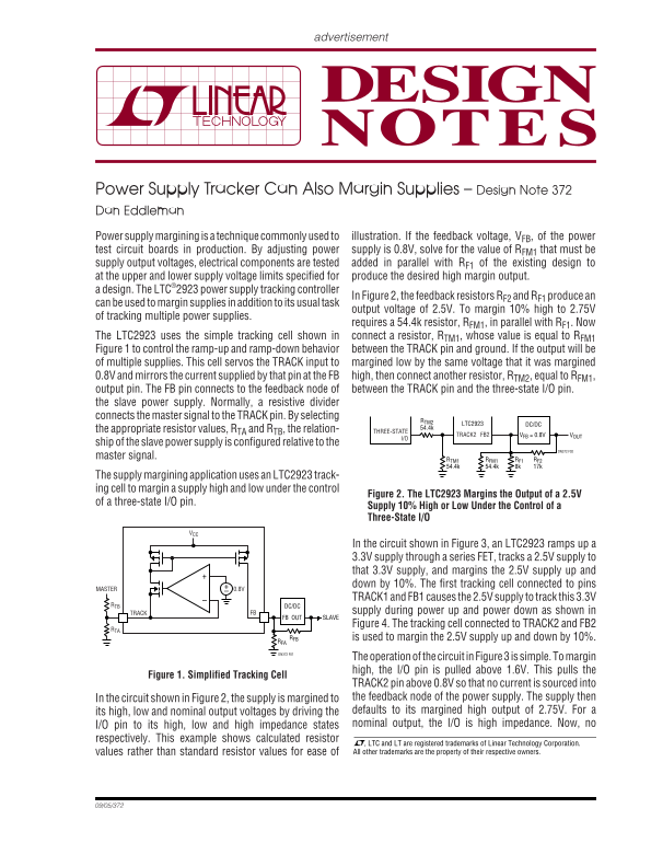
Power Supply Tracker Can Also Margin Supplies – Design Note 372 Dan Eddleman Power supply margining is a technique commonly used to illustration. If the feedback voltage, VFB, of the power test circuit boards in production. By adjusting power supply is 0.8V, solve for the value of RFM1 that must be supply output voltages, electrical components are tested added in parallel with RF1 of the existing design to at the upper and lower supply voltage limits specified for produce the desired high margin output. a design. The LTC®2923 power supply tracking controller
In Figure 2, the feedback resistors RF2 and RF1 produce an
can be used to margin supplies in addition to its usual task
output voltage of 2.5V. To margin 10% high to 2.75V
of tracking multiple power supplies.
requires a 54.4k resistor, RFM1, in parallel with RF1. Now
The LTC2923 uses the simple tracking cell shown in connect a resistor, RTM1, whose value is equal to RFM1 Figure 1 to control the ramp-up and ramp-down behavior between the TRACK pin and ground. If the output will be of multiple supplies. This cell servos the TRACK input to margined low by the same voltage that it was margined 0.8V and mirrors the current supplied by that pin at the FB high, then connect another resistor, RTM2, equal to RFM1, output pin. The FB pin connects to the feedback node of between the TRACK pin and the three-state I/O pin. the slave power supply. Normally, a resistive divider connects the master signal to the TRACK pin. By selecting
DC/DCLTC2923
the appropriate resistor values, RTA and RTB, the relation- 54.4k
TRACK2 VFB = 0.8VFB2THREE-STATE VOUT
ship of the slave power supply is configured relative to the
DN372 F02
master signal.
RTM1 RFM1 RF1 RF2 54.4k 54.4k 8k 17k
The supply margining application uses an LTC2923 track- ing cell to margin a supply high and low under the control
Figure 2. The LTC2923 Margins the Output of a 2.5V
of a three-state I/O pin.
Supply 10% High or Low Under the Control of a Three-State I/O
In the circuit shown in Figure 3, an LTC2923 ramps up a 3.3V supply through a series FET, tracks a 2.5V supply to that 3.3V supply, and margins the 2.5V supply up and +– down by 10%. The first tracking cell connected to pins
MASTER 0.8V
TRACK1 and FB1 causes the 2.5V supply to track this 3.3V
RTB DC/DC
FB TRACK supply during power up and power down as shown in FB OUT SLAVE Figure 4. The tracking cell connected to TRACK2 and FB2
RFB is used to margin the 2.5V supply up and down by 10%. RFA DN372 F01
The operation of the circuit in Figure 3 is simple. To margin high, the I/O pin is pulled above 1.6V. This pulls the
Figure 1. Simplified Tracking Cell
TRACK2 pin above 0.8V so that no current is sourced into In the circuit shown in Figure 2, the supply is margined to the feedback node of the power supply. The supply then its high, low and nominal output voltages by driving the defaults to its margined high output of 2.75V. For a I/O pin to its high, low and high impedance states nominal output, the I/O is high impedance. Now, no
respectively. This example shows calculated resistor
, LTC and LT are registered trademarks of Linear Technology Corporation. values rather than standard resistor values for ease of All other trademarks are the property of their respective owners.
Page Summary Contents For LINEAR Power Supply Tracker & Margining Application – Design Note 372 by Dan Eddleman
Manual Details
| Brand | Linear |
|---|---|
| Pages | 2 |
| File Size | 73.33 KB |
| Published | June 15, 2026 |
Enter the captcha to get the download link:

Frequently Asked Questions
What is the LTC2923's primary function?
Its primary application is tracking multiple power supplies during ramp-up and ramp-down.
How is the 2.5V supply margined 10% high?
Connect a 54.4k resistor in parallel with R_F1 of the existing design.
How do unequal voltage margins get configured?
Adjust R_TM2; set R_TM2/R_TM1 equal to the ratio of ∆V_LOW to ∆V_HIGH.
How does the I/O pin state affect output margining?
High: margin high, high impedance: nominal, low: margin low.