LINEAR Application Note 119A
Summary
These highly integrated DC/DC µModule Regulator Systems are engineered to power complex, high-current digital systems such as those utilizing FPGAs. Featuring a miniature, self-contained IC form factor, they deliver robust power while maintaining an exceptionally low profile and high efficiency. This manual guides system designers through the electrical performance, current sharing capabilities, and thermal layout techniques necessary to reliably build reliable micro-power solutions that require minimal board space and cooling infrastructure.
Page 1 Text Content
Application Note 119A
April 2008
Powering Complex FPGA-Based Systems Using Highly Integrated DC/DC µModule Regulator Systems Part 1 of 2 Circuit and Electrical Performance Alan Chern and Afshin Odabaee
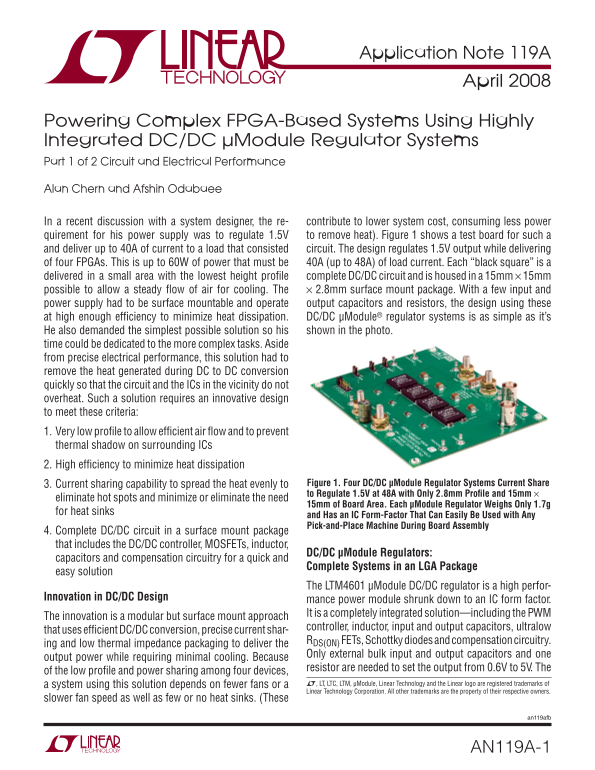
In a recent discussion with a system designer, the re- contribute to lower system cost, consuming less power quirement for his power supply was to regulate 1.5V to remove heat). Figure 1 shows a test board for such a and deliver up to 40A of current to a load that consisted circuit. The design regulates 1.5V output while delivering of four FPGAs. This is up to 60W of power that must be 40A (up to 48A) of load current. Each “black square” is a delivered in a small area with the lowest height profi le complete DC/DC circuit and is housed in a 15mm × 15mm possible to allow a steady fl ow of air for cooling. The × 2.8mm surface mount package. With a few input and power supply had to be surface mountable and operate output capacitors and resistors, the design using these at high enough effi ciency to minimize heat dissipation. DC/DC μModule® regulator systems is as simple as it’s
He also demanded the simplest possible solution so his shown in the photo.
time could be dedicated to the more complex tasks. Aside from precise electrical performance, this solution had to remove the heat generated during DC to DC conversion quickly so that the circuit and the ICs in the vicinity do not overheat. Such a solution requires an innovative design to meet these criteria: 1. Very low profi le to allow effi cient air fl ow and to prevent thermal shadow on surrounding ICs 2. High effi ciency to minimize heat dissipation
3. Current sharing capability to spread the heat evenly to Figure 1. Four DC/DC μModule Regulator Systems Current Share to Regulate 1.5V at 48A with Only 2.8mm Profi le and 15mm ×
eliminate hot spots and minimize or eliminate the need
15mm of Board Area. Each μModule Regulator Weighs Only 1.7g
for heat sinks
and Has an IC Form-Factor That Can Easily Be Used with Any Pick-and-Place Machine During Board Assembly
4. Complete DC/DC circuit in a surface mount package that includes the DC/DC controller, MOSFETs, inductor,
DC/DC μModule Regulators:
capacitors and compensation circuitry for a quick and
Complete Systems in an LGA Package
easy solution
The LTM4601 μModule DC/DC regulator is a high perfor-
Innovation in DC/DC Design mance power module shrunk down to an IC form factor.
It is a completely integrated solution—including the PWM
The innovation is a modular but surface mount approach
controller, inductor, input and output capacitors, ultralow
that uses effi cient DC/DC conversion, precise current shar-
RDS(ON) FETs, Schottky diodes and compensation circuitry.
ing and low thermal impedance packaging to deliver the
Only external bulk input and output capacitors and one
output power while requiring minimal cooling. Because
resistor are needed to set the output from 0.6V to 5V. The
of the low profi le and power sharing among four devices,
a system using this solution depends on fewer fans or a L, LT, LTC, LTM, μModule, Linear Technology and the Linear logo are registered trademarks of Linear Technology Corporation. All other trademarks are the property of their respective owners.
slower fan speed as well as few or no heat sinks. (These
an119afb
AN119A-1
Page Summary Contents For LINEAR Application Note 119A
Manual Details
| Brand | Linear |
|---|---|
| Pages | 4 |
| File Size | 202.03 KB |
| Published | June 16, 2026 |
Enter the captcha to get the download link:

Frequently Asked Questions
How much total current can the LTM4601 achieve when paralleled?
The system is capable of delivering up to 48A of load current.
What are key advantages of using DC/DC μModule Regulator Systems?
They offer a low profile, high efficiency, and integrated circuit form factor for minimal board space.
Does the LTM4601 feature protection against overheating during startup?
Yes, the soft-start feature prevents large inrush currents by slowly ramping the output voltage.