LINEAR Application Note 94 Documentation User Guide
Summary
This technical guide details slew rate, a critical specification measuring an amplifier's maximum rapid change of output voltage, which is vital for high-speed circuit integrity. It covers complex measurement techniques and theory necessary to verify amplifier performance in wideband applications, including A/D drivers and data acquisition systems. Designed for electrical engineers and hardware designers who must ensure signal fidelity and low distortion across demanding analog paths.
Page 1 Text Content
Application Note 94
May 2003
Slew Rate Verification for Wideband Amplifiers The Taming of the Slew Jim Williams
INTRODUCTION Slew rate defines an amplifier’s maximum rate of output total elapsed time from input application until the output excursion. This specification sets limits on undistorted arrives at and remains within a specified error band bandwidth, an important capability in A/D driver applica- around the final value is the settling time.1 tions. Slew rate also influences achievable performance in
Slew rate, normally measured during the middle 2/3
D/A output stages, filters, video amplification and data
of output movement at A␣ =␣ +1, is expressed in volts/
acquisition. Because of its importance, amplifier slew rate
microsecond. Discounting the initial and final move-
must be verified by measurement. Deriving a measure-
ment intervals ensures that amplifier gain-bandwidth
ment approach requires understanding slew rate’s rela-
limitations during partial input overdrive do not influ-
tionship to amplifier dynamics.
ence the measurement.
Amplifier Dynamic Response Historically, slew rate measurement has been relatively
simple.2 Early amplifiers had slew rates of typically 1V/µs,
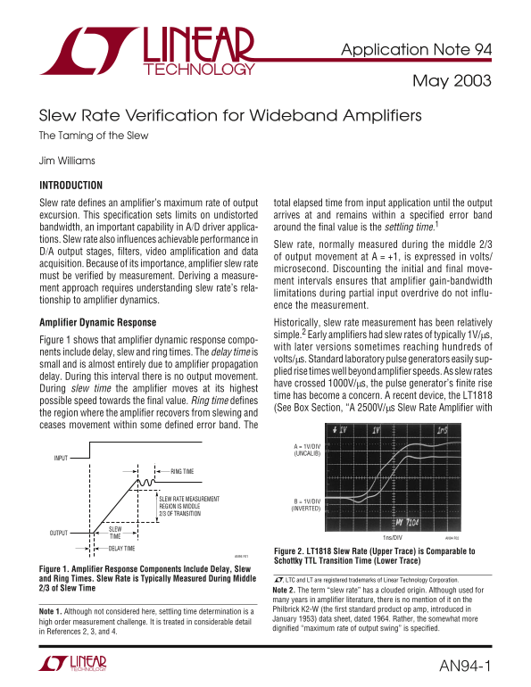
Figure 1 shows that amplifier dynamic response compo-
with later versions sometimes reaching hundreds of
nents include delay, slew and ring times. The delay time is
volts/µs. Standard laboratory pulse generators easily sup-
small and is almost entirely due to amplifier propagation
plied rise times well beyond amplifier speeds. As slew rates
delay. During this interval there is no output movement.
have crossed 1000V/µs, the pulse generator’s finite rise
During slew time the amplifier moves at its highest
time has become a concern. A recent device, the LT1818
possible speed towards the final value. Ring time defines
(See Box Section, “A 2500V/µs Slew Rate Amplifier with
the region where the amplifier recovers from slewing and ceases movement within some defined error band. The
A = 1V/DIV (UNCALIB)
INPUT
RING TIME
SLEW RATE MEASUREMENT
B = 1V/DIV
REGION IS MIDDLE
(INVERTED)
2/3 OF TRANSITION
OUTPUT
TIME 1ns/DIV AN94 F02
DELAY TIME
Figure 2. LT1818 Slew Rate (Upper Trace) is Comparable to
AN94 F01
Schottky TTL Transition Time (Lower Trace)
Figure 1. Amplifier Response Components Include Delay, Slew and Ring Times. Slew Rate is Typically Measured During Middle , LTC and LT are registered trademarks of Linear Technology Corporation. 2/3 of Slew Time Note 2. The term “slew rate” has a clouded origin. Although used for
many years in amplifier literature, there is no mention of it on the Philbrick K2-W (the first standard product op amp, introduced in
Note 1. Although not considered here, settling time determination is a
January 1953) data sheet, dated 1964. Rather, the somewhat more
high order measurement challenge. It is treated in considerable detail
dignified “maximum rate of output swing” is specified.
in References 2, 3, and 4.
AN94-1
Page Summary Contents For LINEAR Application Note 94 Documentation User Guide
Manual Details
| Brand | Linear |
|---|---|
| Pages | 12 |
| File Size | 579.61 KB |
| Published | June 20, 2026 |
Enter the captcha to get the download link:

Frequently Asked Questions
What does slew rate define for an amplifier?
Slew rate defines an amplifier’s maximum rate of total elapsed time from input application until the output excursion.
What components affect dynamic signal measurement besides slew rate?
Amplifier dynamic response is influenced by delay, ring time, and settling time.
How can I ensure accurate high-frequency signal measurements?
Use 50W “hard line” or Teflon-quality coaxial cable, and the probe must specify insertion loss.
What typical specs characterize a modern slew rate amplifier?
A common model features 2500V/ms (slew rate), 400MHz GBW, and –85dBc distortion at 5MHz.