LINEAR Application Note 103 Data Sheet User Guide
Summary
Master the thermal management of your designs with this comprehensive application note covering the LTM4600 DC/DC μModule regulator. This guide provides critical engineering data, including junction-to-ambient thermal models, power loss characterization, and derating curves for various operating conditions. It helps electrical engineers determine safe operational limits by analyzing performance with or without heatsinks and air flow. Perfect for designers building high-power density circuits who require accurate guidelines to ensure maximum efficiency and reliability in diverse ambient environments.
Page 1 Text Content
Application Note 103 January 2006
LTM4600 DC/DC µModule® Regulator Thermal Performance Eddie Beville, Jian Yin
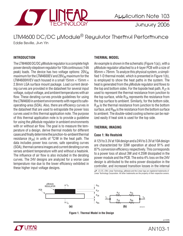
INTRODUCTION THERMAL MODEL The LTM4600 DC/DC μModule regulator is a complete high An example is shown in the schematic (Figure 1(a)), with a power density stepdown regulator for 10A continuous (14A μModule regulator attached to a 4-layer PCB with a size of peak) loads. The device has two voltage options: 20VIN 95mm ¥ 76mm. To analyze this physical system, a simpli- maximum for the LTM4600EV and 28VIN maximum for the fied 1-D thermal model, which is presented in Figure 1(b), LTM4600HVEV each housed in a small 15mm ¥ 15mm ¥ is employed to show the heat paths in the system. The 2.8mm LGA surface mount package. Load current derat- heat is generated from the μModule regulator and flows to ing curves are provided in the datasheet for several input the top and bottom sides. For the topside heat path, RJT is
voltage, output voltage, and ambient temperatures with air used to represent the thermal resistance from junction to flow. These derating curves provide guidelines for using the top surface, while RTA represents the resistance from the LTM4600 in ambient environments with regard to safe- the top surface to ambient. Similarly, for the bottom side, operating-area (SOA). Also, there are efficiency curves in RJB is the thermal resistance from junction to the bottom the datasheet that are used to extrapolate the power loss surface, and RBA is the resistance from the bottom surface curves used in this thermal application note. The purpose to ambient. The double-sided cooling scheme can be real- of this thermal application note is to provide a guideline ized easily if heat sink is used for the top side.
for using the μModule regulator in ambient environments with or without air flow. The goal is to measure the tem-
THERMAL IMAGING
perature of a design, derive thermal models for different cases and finally determine the junction-to-ambient thermal Case 1: No Heatsink resistance (q JA) in units of °C/W in the heat path. The
A 12V to 3.3V at 10A design and a 24V to 3.3V at 10A design
data includes power loss curves, safe operating curves
are characterized for 33W operation at about 91% and
(SOA), thermal camera images and current derating curves
87% conversion effi ciency respectively. This corresponds
verses ambient temperature with and without a heatsink.
to a power loss of about 3W and 4.25W dissipated in the
The influence of air flow is also included in the derating
power module and the PCB. The extra 4% loss on the 24V
curves. The 24V designs are analyzed for a worse case
design is attributed to the extra power dissipation in the
temperature rise due to the lower efficiency exhibited in
controller, and increased transition losses in the internal
these higher input voltage designs.
L, LT, LTC, LTM, Linear Technology, μModule and the Linear logo are registered trademarks of Linear Technology Corporation. All other trademarks are the property of their respective owners.
μModule
RTATA
REGULATOR PCB
RJT RTA
RJB RBA
TA RBA
(b)(a) AN103 F01
Figure 1. Thermal Model in the Design
an103fb
AN103-1
Page Summary Contents For LINEAR Application Note 103 Data Sheet User Guide
Manual Details
| Brand | Linear |
|---|---|
| Pages | 8 |
| File Size | 183.76 KB |
| Published | May 30, 2026 |
Enter the captcha to get the download link:

Frequently Asked Questions
What voltage options does the LTM4600 regulator provide?
The device is available with two primary voltage options: 20V and 28V.
How can I monitor the internal temperature of the µModule regulator?
Insert a thermocouple at a point close to the EXTV pin, ensuring this measurement happens after connecting the main input supply.
How does using an external heatsink improve thermal performance data?
Heatsinks, such as BGA types, significantly decrease the Junction-to-Ambient (R_JA) thermal resistance; for example, it can drop from 15.2 °C/W to 10.25 °C/W.