LINEAR 42V, 2.5A Synchronous Step-Down Regulator with 2.5μA Quiescent Current Design Note 504
Summary
The LT8610 and LT8611 are advanced synchronous step-down regulators designed for high efficiency in demanding environments. These ICs deliver reliable power conversion with ultra-low quiescent current (2.5µA), robust short-circuit tolerance, and flexibility to minimize component size. The manual details optimal circuit designs, demonstrating features like extended input voltage range, constant-current sourcing capabilities, and superior dropout performance. Ideal for engineers developing solutions in automotive, industrial, and communications applications that require highly reliable power management.
Page 1 Text Content
42V, 2.5A Synchronous Step-Down Regulator with 2.5µA Quiescent Current Design Note 504 Hua (Walker) Bai Introduction Short-Circuit Robustness Using Small Inductors The LT®8610 and LT8611 are 42V, 2.5A synchronous The LT8610 and LT8611 are specifi cally designed to step-down regulators that meet the stringent high minimize solution size by allowing inductor size to be input voltage and low output voltage requirements of selected based on the output load requirements of the automotive, industrial and communications applica- application, rather than the maximum current limits of tions. To minimize external components and solution the IC. During overload or short-circuit conditions, the size, the top and bottom power switches are integrated LT8610 and LT8611 safely tolerate operation with satu- in a synchronous regulator topology, including internal rated inductors through the use of a high speed peak-
compensation. The regulator consumes only 2.5μA FF IC IE current mode architecture and a robust switch design.
quiescent current from the input source even while For example, an application that requires a maximum regulating the output. of 1.5A should use an inductor that has an RMS rating
of >1.5A and a saturation current rating of >1.9A. This
High Effi ciency Synchonous Operation
fl exibility allows the user to avoid oversize inductors for
Replacing an external Schottky diode with an internal
applications requiring less than maximum output current.
synchronous power switch not only minimizes the solu-
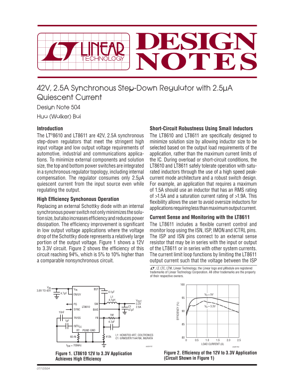
tion size, but also increases effi ciency and reduces power Current Sense and Monitoring with the LT8611 dissipation. The effi ciency improvement is signifi cant The LT8611 includes a fl exible current control and in low output voltage applications where the voltage monitor loop using the ISN, ISP, IMON and ICTRL pins. drop of the Schottky diode represents a relatively large The ISP and ISN pins connect to an external sense portion of the output voltage. Figure 1 shows a 12V resistor that may be in series with the input or output to 3.3V circuit. Figure 2 shows the effi ciency of this of the LT8611 or in series with other system currents. circuit reaching 94%, which is 5% to 10% higher than The current limit loop functions by limiting the LT8611 a comparable nonsynchronous circuit. output current such that the voltage between the ISP L, LT, LTC, LTM, Linear Technology, the Linear logo and μModule are registered trademarks of Linear Technology Corporation. All other trademarks are the property of their respective owners.
BSTVIN
3.8V TO 42V
EN/UV VO = 5V
L1 4.7μH VOUT
PG SW 3.3V
LT8610 C1 2.5A VO = 3.3V
SYNC BIAS 47μF
TR/SS FB 1μF
INTVCC
RT GNDPGND
L1: HCM0703-4R7, COILTRONICS
C1: GRM32ER71A476K, MURATA
LOAD CURRENT (A)
f SW = 700k Hz dn504 F01
dn504 F02
Figure 1. LT8610 12V to 3.3V Application Figure 2. Effi ciency of the 12V to 3.3V Application Achieves High Effi ciency (Circuit Shown in Figure 1)
Page Summary Contents For LINEAR 42V, 2.5A Synchronous Step-Down Regulator with 2.5μA Quiescent Current Design Note 504
Manual Details
| Brand | Current |
|---|---|
| Pages | 2 |
| File Size | 94.64 KB |
| Published | May 18, 2026 |
Enter the captcha to get the download link:

Frequently Asked Questions
What is the quiescent current of the LT8610/LT8611 regulators?
They consume only a very low 2.5µA current from the input source.
How can I monitor or limit the output current on the LT8611?
The LT8611 includes ISN, ISP, and IMON pins for easy monitoring/limiting of short-circuit current using an external sense resistor.
What is the dropout performance like when input voltage drops?
Both regulators maintain high efficiency by skipping switch-off times and keeping the boost capacitor charged during dropout conditions.
Does this regulator support high switching frequencies?
Yes, they are designed for high switching frequencies (e.g., 2MHz), which helps reduce solution size and minimize footprint.