Design Note 465 LINEAR Ultralow Power Boost Converters Require Only 8.5μA of Standby Quiescent Current
Summary
Designed for mission-critical, battery-powered applications like remote monitoring systems, this ultra-low power boost converter provides highly efficient voltage regulation with incredibly low standby quiescent current (as little as 8.5µA). The manual details its performance across varying loads, showcasing superior efficiency and stable ripple voltages even when the circuit is idle or operating from high-impedance sources. Featuring integrated soft-start and output disconnect protection, this converter is ideal for engineers needing to maximize battery life while maintaining reliable power delivery in demanding environments.
Page 1 Text Content
Ultralow Power Boost Converters Require Only 8.5µA of Standby Quiescent Current Design Note 465 Xiaohua Su Introduction effi ciency over a wide load range. Figures 2 and 3 show
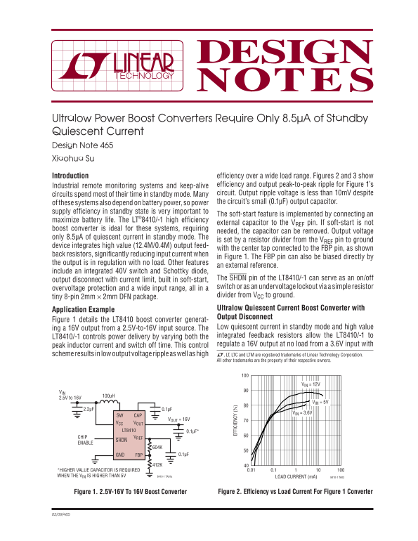
Industrial remote monitoring systems and keep-alive effi ciency and output peak-to-peak ripple for Figure 1’s circuits spend most of their time in standby mode. Many circuit. Output ripple voltage is less than 10m V despite of these systems also depend on battery power, so power the circuit’s small (0.1μF) output capacitor.
supply effi ciency in standby state is very important to
The soft-start feature is implemented by connecting an
maximize battery life. The LT®8410/-1 high effi ciency
external capacitor to the VREF pin. If soft-start is not
boost converter is ideal for these systems, requiring
needed, the capacitor can be removed. Output voltage
FF IC IE
only 8.5μA of quiescent current in standby mode. The
is set by a resistor divider from the VREF pin to ground
device integrates high value (12.4M/0.4M) output feed-
with the center tap connected to the FBP pin, as shown
back resistors, signifi cantly reducing input current when
in Figure 1. The FBP pin can also be biased directly by
the output is in regulation with no load. Other features
an external reference.
include an integrated 40V switch and Schottky diode,
The SHDN pin of the LT8410/-1 can serve as an on/off
output disconnect with current limit, built in soft-start,
switch or as an undervoltage lockout via a simple resistor
overvoltage protection and a wide input range, all in a
divider from VCC to ground.
tiny 8-pin 2mm × 2mm DFN package.
Application Example Ultralow Quiescent Current Boost Converter with Output Disconnect
Figure 1 details the LT8410 boost converter generat-
ing a 16V output from a 2.5V-to-16V input source. The Low quiescent current in standby mode and high value LT8410/-1 controls power delivery by varying both the integrated feedback resistors allow the LT8410/-1 to peak inductor current and switch off time. This control regulate a 16V output at no load from a 3.6V input with
scheme results in low output voltage ripple as well as high L, LT, LTC and LTM are registered trademarks of Linear Technology Corporation.
All other trademarks are the property of their respective owners.
VIN = 12V
2.5V to 16V
VIN = 5V
VIN = 3.6V
SW CAP
VOUT = 16V
VCC VOUT LT8410 0.1μF* CHIP VREF SHDN
ENABLE
GND FBP 0.1μF
*HIGHER VALUE CAPACITOR IS REQUIRED 0.01 100100.1
WHEN THE VIN IS HIGHER THAN 5V 8410-1 TA01a LOAD CURRENT (m A) 8410-1 TA03
Figure 1. 2.5V-16V To 16V Boost Converter Figure 2. Effi ciency vs Load Current For Figure 1 Converter
Page Summary Contents For Design Note 465 LINEAR Ultralow Power Boost Converters Require Only 8.5μA of Standby Quiescent Current
Manual Details
| Brand | Current |
|---|---|
| Pages | 2 |
| File Size | 80.74 KB |
| Published | May 30, 2026 |
Enter the captcha to get the download link:

Frequently Asked Questions
How does the LT8410/-1 conserve battery energy in standby mode?
The device is optimized for ultralow quiescent current, achieving a low standby current of just 8.5µA.
Does the converter have an integrated feature to prevent back-feed during shutdown?
Yes, it includes an output disconnect PMOS switch that physically blocks the load from drawing power from the input source when powered down.
What kind of voltage range is suitable for this boost converter?
It has a wide operating input voltage range, successfully managing inputs from 2.5V up to 16V.
Is this device suitable for high-current demands?
No; it is not designed to replace standard DC/DC converters when applications require very large output currents or risk of voltage collapse.