LINEAR High Efficiency 2-Phase Boost Converter - Minimizes Input & Output Current Ripple – Design Note 371 Data Sheet User Manual
Summary
Optimize your DC/DC power supply design with this controller for creating high-efficiency, low-ripple boost converters. This technical manual details the superior performance of a dual-phase boosting topology compared to single-phase designs. It provides deep insights into reducing input and output ripple currents and minimizing EMI—critical considerations for demanding industrial and automotive power applications requiring reliable operation at higher wattage levels.
Page 1 Text Content
High Efficiency 2-Phase Boost Converter Minimizes Input and Output Current Ripple – Design Note 371 Goran Perica
Introduction also increase proportional to the output-to-input voltage conversion ratio, so if the input voltage is low, the
Many automotive and industrial applications require higher
switching currents can overwhelm a simple boost con-
voltages than is available on the input power supply rail.
verter and generate unacceptable EMI.
A simple DC/DC boost converter suffices when the power levels are in the 10W to 50W range, but if higher power
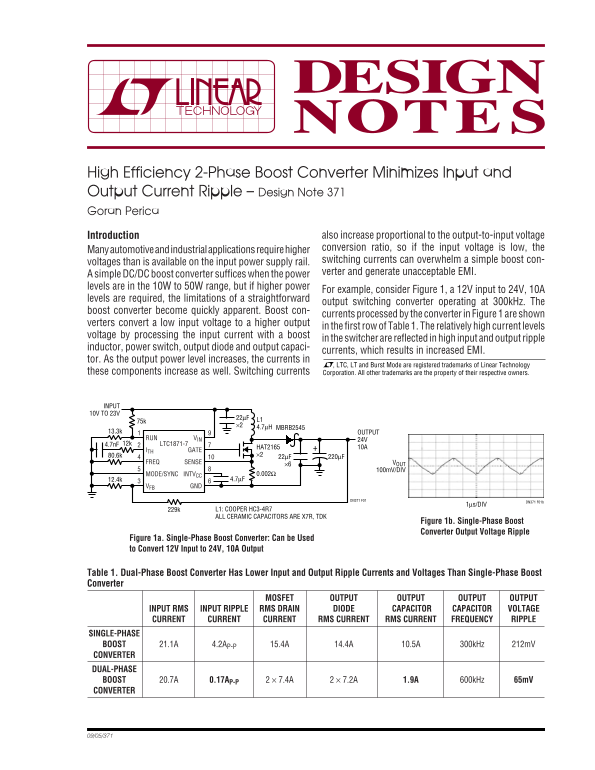
For example, consider Figure 1, a 12V input to 24V, 10A
levels are required, the limitations of a straightforward
output switching converter operating at 300k Hz. The
boost converter become quickly apparent. Boost con-
currents processed by the converter in Figure 1 are shown
verters convert a low input voltage to a higher output
in the first row of Table 1. The relatively high current levels
voltage by processing the input current with a boost
in the switcher are reflected in high input and output ripple
inductor, power switch, output diode and output capaci-
currents, which results in increased EMI.
tor. As the output power level increases, the currents in
, LTC, LT and Burst Mode are registered trademarks of Linear Technology
these components increase as well. Switching currents Corporation. All other trademarks are the property of their respective owners.
INPUT 10V TO 23V
MBRB2545
13.3k OUTPUT
RUN VIN 24V
12k4.7n F LTC1871-7
HAT2165 10A
ITH GATE
FREQ SENSE VOUT
100m V/DIV
MODE/SYNC INTVCC 0.002Ω
VFB GND
DN371 F01 DN371 F01b
1μs/DIV
229k L1: COOPER HC3-4R7 ALL CERAMIC CAPACITORS ARE X7R, TDK
Figure 1b. Single-Phase Boost Converter Output Voltage Ripple
Figure 1a. Single-Phase Boost Converter: Can be Used to Convert 12V Input to 24V, 10A Output
Table 1. Dual-Phase Boost Converter Has Lower Input and Output Ripple Currents and Voltages Than Single-Phase Boost Converter
MOSFET OUTPUT OUTPUT OUTPUT OUTPUT
INPUT RMS INPUT RIPPLE RMS DRAIN DIODE CAPACITOR CAPACITOR VOLTAGE CURRENT CURRENT CURRENT RMS CURRENT RMS CURRENT FREQUENCY RIPPLE
SINGLE-PHASE
BOOST 21.1A 4.2AP-P 15.4A 14.4A 10.5A 300k Hz 212m V
CONVERTER DUAL-PHASE BOOST 20.7A 0.17AP-P 2 × 7.4A 2 × 7.2A 1.9A 600k Hz 65m V CONVERTER
Page Summary Contents For LINEAR High Efficiency 2-Phase Boost Converter - Minimizes Input & Output Current Ripple – Design Note 371 Data Sheet User Manual
Manual Details
| Brand | Current |
|---|---|
| Pages | 2 |
| File Size | 117.69 KB |
| Published | May 18, 2026 |
Enter the captcha to get the download link:

Frequently Asked Questions
What is the primary advantage of using a dual-phase boost converter?
It interleaves power output, which significantly lowers input and output ripple currents and voltages compared to single-phase designs.
How does this design help minimize Electromagnetic Interference (EMI)?
By reducing input and output current ripples through interleaving power output, the overall EMI is significantly reduced.
When is a simple boost converter sufficient for my application?
A simple DC/DC boost converter suffices when operating at lower power levels, such as the 10W to 50W range.