LINEAR Monolithic Synchronous Step-Down Regulator for High Current Output and Wider Input Voltage Range - Design Note 457
Summary
Designed for power electronics engineers, this manual provides detailed information on the LTC36XX family of high-power monolithic synchronous regulators. This series delivers extremely efficient DC/DC conversion—up to 24A in parallel—with a remarkably small footprint and minimal external components. It is ideal for designing robust industrial or communications systems that require reliable operation across wide input voltages, fast transient response, and advanced protection features like overvoltage and current limiting.
Page 1 Text Content
Monolithic Synchronous Step-Down Regulator Delivers up to 12A from a Wide Input Voltage Range – Design Note 457 Charlie Zhao and Henry Zhang
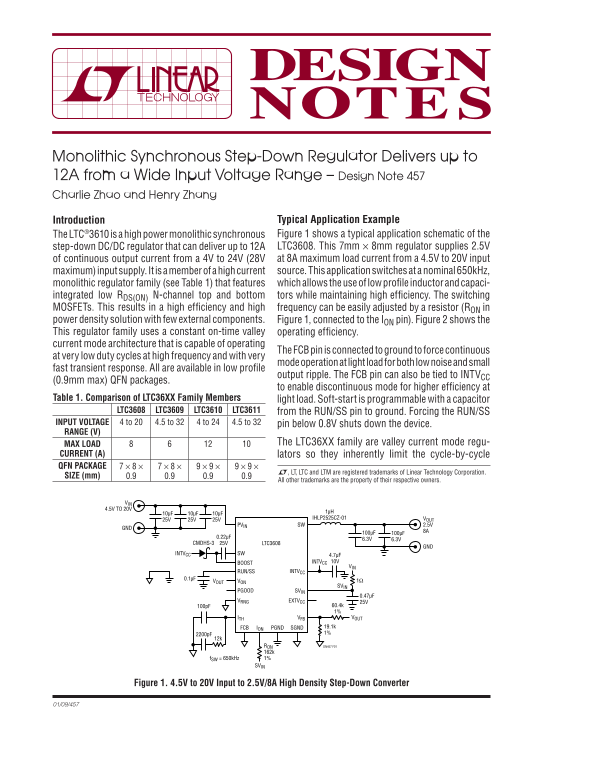
Introduction Typical Application Example The LTC®3610 is a high power monolithic synchronous Figure 1 shows a typical application schematic of the step-down DC/DC regulator that can deliver up to 12A LTC3608. This 7mm × 8mm regulator supplies 2.5V of continuous output current from a 4V to 24V (28V at 8A maximum load current from a 4.5V to 20V input maximum) input supply. It is a member of a high current source. This application switches at a nominal 650k Hz, monolithic regulator family (see Table 1) that features which allows the use of low profi le inductor and capaci-
integrated low RDS(ON) N-channel top and bottom tors while maintaining high effi ciency. The switching MOSFETs. This results in a high effi ciency and high frequency can be easily adjusted by a resistor (RON in power density solution with few external components. Figure 1, connected to the ION pin). Figure 2 shows the This regulator family uses a constant on-time valley operating effi ciency. current mode architecture that is capable of operating
The FCB pin is connected to ground to force continuous
at very low duty cycles at high frequency and with very
mode operation at light load for both low noise and small
fast transient response. All are available in low profi le
output ripple. The FCB pin can also be tied to INTVCC
(0.9mm max) QFN packages.
to enable discontinuous mode for higher effi ciency at
Table 1. Comparison of LTC36XX Family Members light load. Soft-start is programmable with a capacitor
LTC3608 LTC3609 LTC3610 LTC3611 from the RUN/SS pin to ground. Forcing the RUN/SS
INPUT VOLTAGE 4 to 20 4.5 to 32 4 to 24 4.5 to 32 pin below 0.8V shuts down the device. RANGE (V)
MAX LOAD The LTC36XX family are valley current mode regu-
CURRENT (A) lators so they inherently limit the cycle-by-cycle QFN PACKAGE 7 × 8 × 7 × 8 × 9 × 9 × 9 × 9 ×
L, LT, LTC and LTM are registered trademarks of Linear Technology Corporation.
SIZE (mm) 0.9 0.9 0.9 0.9
All other trademarks are the property of their respective owners.
4.5V TO 20V
10μF 10μF 10μF 1μH 25V 25V 25V IHLP2525CZ-01 VOUT
PVIN SW 2.5V
CMDHS-3 25V LTC3608
INTVCC SW 4.7μF
BOOST INTVCC 10V VIN
INTVCCRUN/SS
VONVOUT 1Ω SVIN
PGOOD SVIN
VRNG EXTVCC 25V
ITH VFB VOUT
ION PGND SGNDFCB 19.1k 2200p F 1%
RON DN457 F01 162k
f SW = 650k Hz 1%
Figure 1. 4.5V to 20V Input to 2.5V/8A High Density Step-Down Converter
Page Summary Contents For LINEAR Monolithic Synchronous Step-Down Regulator for High Current Output and Wider Input Voltage Range - Design Note 457
Manual Details
| Brand | Current |
|---|---|
| Pages | 2 |
| File Size | 73.17 KB |
| Published | May 18, 2026 |
Enter the captcha to get the download link:

Frequently Asked Questions
What is the typical operating current range for the LTC3610 regulator?
It delivers up to 12A of continuous output current from a wide input voltage range of 4V to 24V.
Can the LTC3610 be used in high-current applications requiring more than 12A?
Yes, the parts can be easily paralleled for higher output current applications, such as delivering 24A using two LTC3610s.
How is current sensing handled when paralleling regulators like the LTC3610?
The feedback pins of paralleled units share a single voltage point, and no additional DS(ON) current sense resistor is required.
What happens if the output voltage drops dramatically (short circuit)?
When the output drops more than 1 V below the nominal target, the internal top MOSFET turns off and the bottom MOSFET turns on until the transient condition clears.