LINEAR Simple Battery Circuit for PoE Extension – Peak Current Limitation – Design Note DN361
Summary
Design, deploy, and understand advanced PowerPath solutions that overcome standard PoE limitations. This manual details the LTC4055 circuit, a highly integrated system designed to sustain continuous power supply by seamlessly augmenting fixed 5V Ethernet PoE with stored battery reserves. It is perfect for engineers requiring robust, dependable DC power management in applications where transient or peak current demands may exceed typical PoE standards.
Page 1 Text Content
advertisement
Simple Battery Circuit Extends Power over Ethernet (Po E) Peak Current – Design Note 361 Mark Gurries
Introduction devices. The Po E specification also sets an upper limit on Power over Ethernet (Po E) is a new development that the power that can be drawn by a PD. The problem is: what happens when a PD must draw more power than allowed
allows for the delivery of power to Ethernet-based devices
by the Po E standard? Examples may be the spin up of a
via standard Ethernet CAT5 cable, precluding the need for
disk drive or a period of sustained transmission of data
wall adapters or other external power sources. The Po E
from an RF transmitter. If the average power load of these
specification defines a hardware detection protocol where Power Sourcing Equipment (PSE) is able to identify Po E
, LTC and LT are registered trademarks of Linear Technology Corporation.
Powered Devices (PDs), thus allowing full backwards
Power Path is a trademark of Linear Technology Corporation. compatibility with non-Po E-aware (legacy) Ethernet All other trademarks are the property of their respective owners.
PA1134 5V POE 5V C3 1.8A
1µF 68p F SMB540
ETHERNET R3
AC1 BR2
8.2V 6.3V OS-CON
D3 FROM Q2 R6 BAS516 DATA MMBTA42 510Ω
PAIR C4
AC2 HDO1
LTC4267 Q1
C1 Si3440DV
AC1 BR1
0.1µF PVCC NGATE
NC SENSE
FROM X7R R4
SPARE 0.125Ω R21
VPORTP VFB
PAIR 1% 1/4W 470Ω
4.7µF RCLASS ITH/RUN
SMAJ58A Q3 C12
AC2 HDO1 1µF R11 C13
SIGDISA PWRGD 2N7002
VPORTIN POUT D7 R13
1,8,9,16 BAS516 100k
R1 1% D4 10k BAS516 PS2911
PVCC 27n F
UPS340 100k 6.8k
TO DC/DC
5V POE
CONVERTERS D8 R14
R15 ZRL431 33.2k
LTC4055
1-CELL 4.2V
WALL OUT 10µF
Li-Ion
R16 6.3V DN361 F01C8 2.2n F
10k SHDN BAT
250V AC YCAP
SUSP TIMER HPWR CLPROG
ACPR PROG
CHRG GND
TO HOST
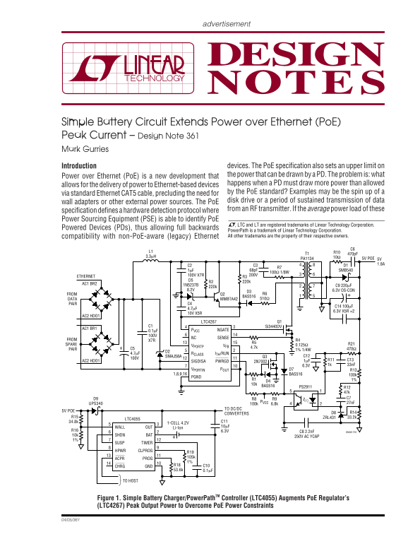
Figure 1. Simple Battery Charger/Power Path TM Controller (LTC4055) Augments Po E Regulator’s (LTC4267) Peak Output Power to Overcome Po E Power Constraints
Page Summary Contents For LINEAR Simple Battery Circuit for PoE Extension – Peak Current Limitation – Design Note DN361
Manual Details
| Brand | Current |
|---|---|
| Pages | 2 |
| File Size | 71.04 KB |
| Published | May 18, 2026 |
Enter the captcha to get the download link:

Frequently Asked Questions
How does the circuit augment PoE power when it is insufficient?
The LTC4055 solution stores power in the PD, and then taps this reserve to automatically switch over to supplement the PoE supply.
What kind of devices can run on the modified PowerPath?
Powered devices connected to the OUT pin must be compatible with the Li-Ion voltage range.
Is there a delay when switching from battery power to PoE power?
No, the change is seamless and happens "on the fly," so power is never lost.
What is the maximum output of the LTC4267 circuit shown?
It supplies 5V at 1.8A.