LINEAR AN4-1 datasheet
Summary
High-performance power buffer designed for driving difficult and reactive loads, including capacitive and non-linear circuits. This technical manual provides detailed applications, helping engineers integrate the LT1010 into complex designs like video line drivers and sample-hold buffers. Ideal for circuit designers who require reliable signal isolation, fast response time, and robust protection against thermal or current overloads in demanding analog systems.
Page 1 Text Content
Application Note 4 September 1984
Applications for a New Power Buffer Jim Williams
A frequent requirement in systems involves driving Buffered Output Line Driver analog signals into non-linear or reactive loads. Cables,
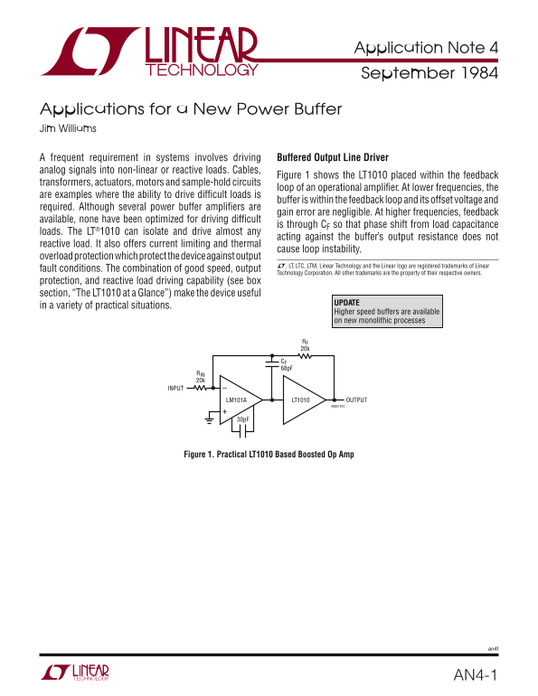
Figure 1 shows the LT1010 placed within the feedback
transformers, actuators, motors and sample-hold circuits
loop of an operational amplifi er. At lower frequencies, the
are examples where the ability to drive diffi cult loads is
buffer is within the feedback loop and its offset voltage and
required. Although several power buffer amplifi ers are
gain error are negligible. At higher frequencies, feedback
available, none have been optimized for driving diffi cult
is through CF so that phase shift from load capacitance
loads. The LT®1010 can isolate and drive almost any
acting against the buffer’s output resistance does not
reactive load. It also offers current limiting and thermal
cause loop instability.
overload protection which protect the device against output
L, LT, LTC, LTM, Linear Technology and the Linear logo are registered trademarks of Linear
fault conditions. The combination of good speed, output
Technology Corporation. All other trademarks are the property of their respective owners.
protection, and reactive load driving capability (see box section, “The LT1010 at a Glance”) make the device useful
UPDATE
in a variety of practical situations.
Higher speed buffers are available on new monolithic processes
RF 20k
CF 68p F
RIN 20k
INPUT
LT1010LM101A OUTPUT AN04 F01
Figure 1. Practical LT1010 Based Boosted Op Amp
AN4-1
Page Summary Contents For LINEAR AN4-1 datasheet
Manual Details
| Brand | Linear |
|---|---|
| Pages | 8 |
| File Size | 989.47 KB |
| Published | June 06, 2026 |
Enter the captcha to get the download link:

Frequently Asked Questions
What is the LT1010's primary use case?
It can isolate and drive almost any reactive load, such as transformers or motors, in feedback circuits.
How does the LT1010 protect against faults?
The device includes current limiting and thermal overload protection to guard against fault conditions like high currents or temperature excursions.
What characterizes the LT1010's performance when driving capacitive loads?
It is suitable for driving large capacitive loads (> 1µF) while maintaining good DC characteristics due to its design optimization.
Are there physical requirements for optimal operation?
For high power applications, especially with TO-39 packages, heat sinking or mounting on a PCB may be required to manage thermal resistance and prevent overheating.