Intel Silicon InterSil AN9824 SPICE Model Tutorial: RSLIC18 AC Loop Data Sheet Manual
Summary
The RSLIC18 family of ICs provides critical circuit functionality for high-accuracy voice line signaling. This technical application note serves as a comprehensive SPICE Model Tutorial, guiding engineers through the detailed AC loop architecture. It thoroughly explains signal transmission paths, covering everything from ultra-stable sense current sensing to impedance synthesis and differential output generation. Ideal for electrical designers and simulation specialists working on advanced communication systems requiring robust performance matching temperature variability.
Page 1 Text Content
查询RSLIC18供应商
SPICE Model Tutorial of the RSLIC18™ AC Loop TM
Application Note October 1998 AN9824
The AC loop of the RSLIC18 providing superb matching, temperature stability and gain refers to the voice band path accuracies.
which provides full duplex
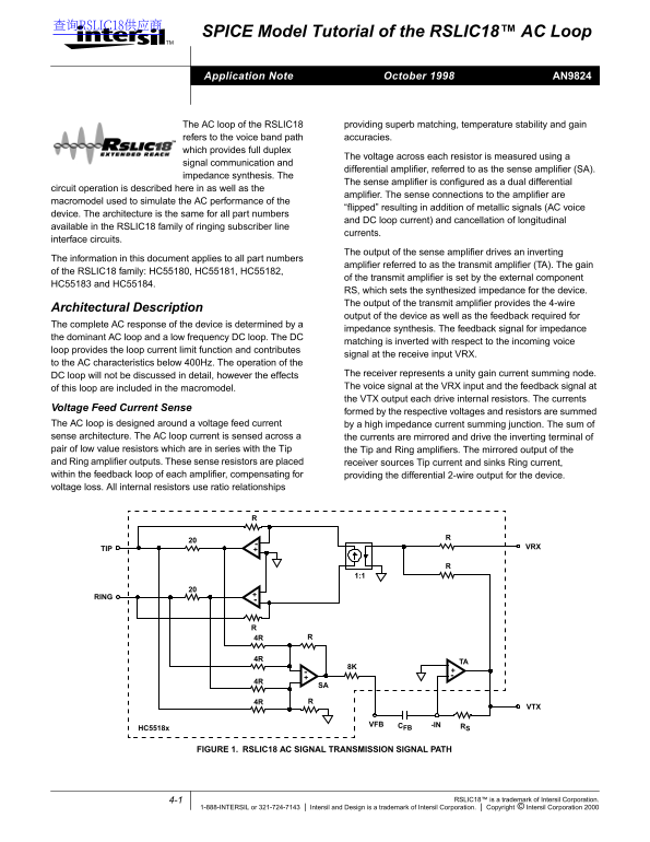
The voltage across each resistor is measured using a
signal communication and
differential amplifier, referred to as the sense amplifier (SA).
impedance synthesis. The
The sense amplifier is configured as a dual differential
circuit operation is described here in as well as the
amplifier. The sense connections to the amplifier are
macromodel used to simulate the AC performance of the
“flipped” resulting in addition of metallic signals (AC voice
device. The architecture is the same for all part numbers
and DC loop current) and cancellation of longitudinal
available in the RSLIC18 family of ringing subscriber line
currents.
interface circuits.
The output of the sense amplifier drives an inverting
The information in this document applies to all part numbers
amplifier referred to as the transmit amplifier (TA). The gain
of the RSLIC18 family: HC55180, HC55181, HC55182,
of the transmit amplifier is set by the external component
HC55183 and HC55184.
RS, which sets the synthesized impedance for the device. The output of the transmit amplifier provides the 4-wire
Architectural Description
output of the device as well as the feedback required for
The complete AC response of the device is determined by
impedance synthesis. The feedback signal for impedance
the dominant AC loop and low frequency DC loop. The DC
matching is inverted with respect to the incoming voice
loop provides the loop current limit function and contributes
signal at the receive input VRX.
to the AC characteristics below 400Hz. The operation of the
DC loop will not be discussed in detail, however the effects The receiver represents unity gain current summing node. of this loop are included in the macromodel. The voice signal at the VRX input and the feedback signal at the VTX output each drive internal resistors. The currents
Voltage Feed Current Sense
formed by the respective voltages and resistors are summed
The AC loop is designed around a voltage feed current by a high impedance current summing junction. The sum of sense architecture. The AC loop current is sensed across a the currents are mirrored and drive the inverting terminal of pair of low value resistors which are in series with the Tip the Tip and Ring amplifiers. The mirrored output of the and Ring amplifier outputs. These sense resistors are placed receiver sources Tip current and sinks Ring current, within the feedback loop of each amplifier, compensating for providing the differential 2-wire output for the device. voltage loss. All internal resistors use ratio relationships
TIP VRX
VFB -IN RSCFB
HC5518x
FIGURE 1. RSLIC18 AC SIGNAL TRANSMISSION SIGNAL PATH
4-1 RSLIC18™ is a trademark of Intersil Corporation.
1-888-INTERSIL or 321-724-7143 Intersil and Design is a trademark of Intersil Corporation. Copyright © Intersil Corporation 2000
Page Summary Contents For Intel Silicon InterSil AN9824 SPICE Model Tutorial: RSLIC18 AC Loop Data Sheet Manual
Manual Details
| Brand | Intel |
|---|---|
| Pages | 10 |
| File Size | 114.45 KB |
| Published | May 30, 2026 |
Enter the captcha to get the download link:

Frequently Asked Questions
What role does the Sense Amplifier play in the RSLIC18 circuit?
It uses signal communication and a differential amplifier to measure voltage, which is crucial for providing full duplex impedance synthesis.
How is the gain of the Transmit Amplifier (TA) set on the RSLIC18?
The TA gain is controlled by external components identified as HC55183 and HC55184.
Is the core architecture different between various RSLIC18 part numbers?
No, the document confirms that 'The architecture is the same for all part numbers' within the RSLIC18 family.