Intel.Intersil ISL1535 Specifications
Summary
The ISL1535 is a high-performance, low-power dual-channel differential output driver ideal for central office line applications such as ADSL2+, VDSL, and G.SHDSL systems. It offers extended bandwidth and low Total Harmonic Distortion (THD) with configurable power modes to optimize efficiency. This manual provides comprehensive technical specifications, detailed operational parameters, electrical characteristics, and application guidelines needed by hardware engineers designing advanced digital subscriber line (DSL) communication equipment.
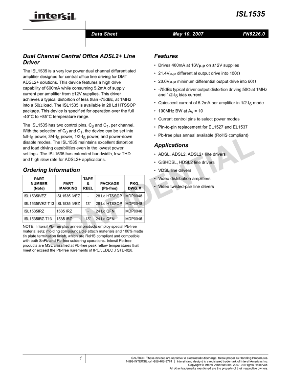
Page 1 Text Content
ISL1535
Data Sheet May 10, 2007 FN6226.0
Dual Channel Central Office ADSL2+ Line Features Driver
Drives 400m A at 16VP-P on ±12V supplies
The ISL1535 is a very low power dual channel differentiated
21.4VP-P differential output drive into 100Ω
amplifier designed for central office line driving for DMT
ADSL2+ solutions. This device features a high drive 20.6VP-P minimum differential output drive into 60Ω
capability of 600m A while consuming 5.2m A of supply
-75d Bc typical driver output distortion driving 50Ω at 1MHz
current per amplifier from ±12V supplies. This driver and 1/2-IS bias current achieves a typical distortion of less than -75d Bc, at 1MHz
Quiescent current of 5.2m A per amplifier in 1/2-IS mode
into a 50Ω load. The ISL1535 is available in 28 Ld HTSSOP package. This device is specified for operation over the full 100MHz BW at AV = 10 -40°C to +85°C temperature range.
Current control pins to select power modes
The ISL1535 has two control pins, C0 and C1, per channel.
Pin-to-pin replacement for EL1527 and EL1537
With the selection of C0 and C1, the device can be set into
Pb-free plus anneal available (Ro HS compliant)
full-IS power, 3/4-IS power, 1/2-IS power, and power-down disable modes. The ISL1535 maintains excellent distortion
Applications
and load driving capabilities even in the lowest power settings. The ISL1535 has extended bandwidth, low THD ADSL, ADSL2, ADSL2+ line drivers and high slew rate for ADSL2+ applications.
G.SHDSL, HDSL2 line drivers
Ordering Information VDSL line drivers
PART TAPE Video distribution amplifiers
NUMBER PART PACKAGE PKG.
Video twisted-pair line drivers
(Note) MARKING REEL (Pb-free) DWG. #
ISL1535IVEZ ISL1535 IVEZ 28 Ld HTSSOP MDP0048
ISL1535IVEZ-T13 ISL1535 IVEZ 13” 28 Ld HTSSOP MDP0048
ISL1535IRZ 1535 IRZ 24 Ld QFN MDP0046
ISL1535IRZ-T13 1535 IRZ 13” 24 Ld QFN MDP0046
NOTE: Intersil Pb-free plus anneal products employ special Pb-free material sets; molding compounds/die attach materials and 100% matte tin plate termination finish, which are Ro HS compliant and compatible with both Sn Pb and Pb-free soldering operations. Intersil Pb-free products are MSL classified at Pb-free peak reflow temperatures that meet or exceed the Pb-free ruirements of IPC/JEDEC J STD-020.
CAUTION: These devices are sensitive to electrostatic discharge; follow proper IC Handling Procedures.
1-888-INTERSIL or1-888-468-3774 Intersil (and design) is a registered trademark of Intersil Americas Inc. Copyright © Intersil Americas Inc. 2007. All Rights Reserved. All other trademarks mentioned are the property of their respective owners.
Page Summary Contents For Intel.Intersil ISL1535 Specifications
Manual Details
| Brand | Intel |
|---|---|
| Pages | 12 |
| File Size | 254.40 KB |
| Published | May 30, 2026 |
Enter the captcha to get the download link:

Frequently Asked Questions
How should I select different power consumption modes for this device?
You can use the two control pins ($C_0B$ and $C_1B$) to set the device into full-I, 3/4-I, 1/2-I, or power-down disable modes.
What is the operational bandwidth of the ISL1535 line driver?
The device is specified for operation over a full 100MHz bandwidth at an A = 10 V.
Is this component susceptible to electrostatic discharge (ESD)?
Yes, the manual warns that these devices are sensitive to electrostatic discharge; proper IC Handling Procedures must be followed.
Are the ISL1535 products compliant with modern lead-free standards?
The device is available in a Pb-free plus anneal version and is RoHS compliant.