Page 1
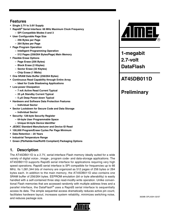
Features Single 2.7V to 3.6V Supply Rapid S® Serial Interface: 66 MHz Maximum Clock Frequency SPI Compatible Modes 0 and 3 User Configurable Page Size 256 Bytes per Page 264 Bytes per Page Page Progra...
Page 2
The device is optimized for use in many commercial and industrial applications where high-den- sity, low-pin count, low-voltage and low-power are essential. To allow for simple in-system reprogrammabi...
Page 3
AT45DB011D [Preliminary] Figure 2-1. SOIC Top View Figure 2-2. MLF Top View(1) SI SO SI SO SCK GND SCK GND RESET VCC RESET VCC CS WP CS WP Note: 1. The metal pad on the bottom of the MLF package is fl...
Page 4
4. Memory Array To provide optimal flexibility, the memory array of the AT45DB011D is divided into three levels of granularity comprising of sectors, blocks, and pages. The “Memory Architecture Diagra...
Page 5
AT45DB011D [Preliminary] 6. Read Commands By specifying the appropriate opcode, data can be read from the main memory or from the SRAM data buffer. The Data Flash supports Rapid S protocols for Mode 0...
Page 6
The CS pin must remain low during the loading of the opcode, the address bytes, and the read- ing of data. When the end of a page in the main memory is reached during a Continuous Array Read, the devi...
Page 7
AT45DB011D [Preliminary] reached, the device will continue reading back at the beginning of the same page. A low-to-high transition on the CS pin will terminate the read operation and tri-state the ou...
Page 8
will first erase the selected page in main memory (the erased state is a logic 1) and then pro- gram the data stored in the buffer into the specified page in main memory. Both the erase and the progra...
Page 9
AT45DB011D [Preliminary] Table 7-1. Block Erase Addressing PA8/ PA7/ PA6/ PA5/ PA4/ PA3/ PA2/ PA1/ PA0/ A16 A15 A14 A13 A12 A11 A10 A9 A8 Block 7.6 Sector Erase The Sector Erase command can be used to...
Page 10
Table 7-2. Sector Erase Addressing PA8/ PA7/ PA6/ PA5/ PA4/ PA3/ PA2/ PA1/ PA0/ A16 A15 A14 A13 A12 A11 A10 A9 A8 Sector 7.7 Chip Erase The entire main memory can be erased at one time by using the Ch...
Page 11
AT45DB011D [Preliminary] 7.8 Main Memory Page Program Through Buffer This operation is a combination of the Buffer Write and Buffer to Main Memory Page Program with Built-in Erase operations. Data is ...
Page 12
8.1 Software Sector Protection 8.1.1 Enable Sector Protection Command Sectors specified for protection in the Sector Protection Register can be protected from program and erase operations by issuing t...
Page 13
AT45DB011D [Preliminary] 9. Hardware Controlled Protection Sectors specified for protection in the Sector Protection Register and the Sector Protection Reg- ister itself can be protected from program ...
Page 14
9.1 Sector Protection Register The nonvolatile Sector Protection Register specifies which sectors are to be protected or unpro- tected with either the software or hardware controlled protection method...
Page 15
AT45DB011D [Preliminary] 9.1.1 Erase Sector Protection Register Command In order to modify and change the values of the Sector Protection Register, it must first be erased using the Erase Sector Prote...
Page 16
9.1.2 Program Sector Protection Register Command Once the Sector Protection Register has been erased, it can be reprogrammed using the Program Sector Protection Register command. To program the Sector...
Page 17
AT45DB011D [Preliminary] 9.1.3 Read Sector Protection Register Command To read the Sector Protection Register, the CS pin must first be asserted. Once the CS pin has been asserted, an opcode of 32H an...
Page 18
10. Security Features 10.1 Sector Lockdown The device incorporates a Sector Lockdown mechanism that allows each individual sector to be permanently locked so that it becomes read only. This is useful ...
Page 19
AT45DB011D [Preliminary] 10.1.1 Sector Lockdown Register Sector Lockdown Register is a nonvolatile register that contains 4 bytes of data, as shown below: Sector Number 0 (0a, 0b) 1 to 3 Locked FFH Se...
Page 20
10.2 Security Register The device contains a specialized Security Register that can be used for purposes such as unique device serialization or locked key storage. The register is comprised of a total...
Page 21
AT45DB011D [Preliminary] 10.2.2 Reading the Security Register The Security Register can be read by first asserting the CS pin and then clocking in an opcode of 77H followed by three dummy bytes. After...
Page 22
the data bytes in the buffer. During this time (t COMP), the status register will indicate that the part is busy. On completion of the compare operation, bit 6 of the status register is updated with t...
Page 23
AT45DB011D [Preliminary] data in the buffer. If bit 6 is a 1, then at least one bit of the data in the main memory page does not match the data in the buffer. Bit 1 in the Status Register is used to p...
Page 24
12. Deep Power-down After initial power-up, the device will default in standby mode. The Deep Power-down command allows the device to enter into the lowest power consumption mode. To enter the Deep Po...
Page 25
AT45DB011D [Preliminary] 13. “Power of 2” Binary Page Size Option “Power of 2” binary page size Configuration Register is a user-programmable nonvolatile regis- ter that allows the page size of the ma...
Page 26
14.1 Manufacturer and Device ID Information 14.1.1 Byte 1 – Manufacturer ID JEDEC Assigned Code Hex Value Bit 7 Bit 6 Bit 5 Bit 4 Bit 3 Bit 2 Bit 1 Bit 0 1FH Manufacturer ID 1FH = Atmel 14.1.2 Byte 2 ...
Page 27
AT45DB011D [Preliminary] 14.2 Operation Mode Summary The commands described previously can be grouped into four different categories to better describe which commands can be executed at what times. Gr...
Page 28
15. Command Tables Table 15-1. Read Commands Command Opcode Main Memory Page Read D2H Continuous Array Read (Legacy Command) E8H Continuous Array Read (Low Frequency) 03H Continuous Array Read (High F...
Page 29
AT45DB011D [Preliminary] Table 15-3. Protection and Security Commands Command Opcode Enable Sector Protection 3DH + 2AH + 7FH + A9H Disable Sector Protection 3DH + 2AH + 7FH + 9AH Erase Sector Protect...
Page 30
Table 15-6. Detailed Bit-level Addressing Sequence for Binary Page Size (256 Bytes) Page Size = 256 bytes Address Byte Address Byte Address Byte Additional Don’t Care Opcode Bytes Opcode es er ve es e...
Page 31
AT45DB011D [Preliminary] Table 15-7. Detailed Bit-level Addressing Sequence for Standard Data Flash Page Size (264 Bytes) Page Size = 264 bytes Address Byte Address Byte Address Byte Additional Don’t ...
Page 32
16. Power-on/Reset State When power is first applied to the device, or when recovering from a reset condition, the device will default to Mode 3. In addition, the output pin (SO) will be in a high imp...
Page 33
AT45DB011D [Preliminary] 18. Electrical Specifications Table 18-1. Absolute Maximum Ratings* Temperature under Bias -55°C to +125°C *NOTICE: Stresses beyond those listed under “Absolute Maximum Rating...
Page 34
Table 18-4. AC Characteristics – Rapid S/Serial Interface Symbol Parameter Min Typ Max Units f SCK SCK Frequency MHz f CAR1 SCK Frequency for Continuous Array Read MHz f CAR2 SCK Frequency for Continu...
Page 35
AT45DB011D [Preliminary] 19. Input Test Waveforms and Measurement Levels AC AC DRIVING 1.5V MEASUREMENT LEVELS LEVEL0.45V t R, t F < 2 ns (10% to 90%) 20. Output Test Load DEVICE UNDER TEST 21. AC ...
Page 36
21.1 Waveform 1 – SPI Mode 0 Compatible (for Frequencies up to 66 MHz) t CSS t WH t WL t CSH t V t HO t DIS HIGH IMPEDANCE HIGH IMPEDANCE SO VALID OUT t Ht SU SI VALID IN 21.2 Waveform 2 – SPI Mode 3 ...
Page 37
AT45DB011D [Preliminary] 21.5 Utilizing the Rapid S Function To take advantage of the Rapid S function's ability to operate at higher clock frequencies, a full clock cycle must be used to transmit dat...
Page 38
21.6 Reset Timing t REC t CSS t RST RESET HIGH IMPEDANCE HIGH IMPEDANCE SO (OUTPUT) SI (INPUT) Note: The CS signal should be in the high state before the RESET signal is deasserted. 21.7 Command Seque...
Page 39
AT45DB011D [Preliminary] 22. Write Operations The following block diagram and waveforms illustrate the various write sequences available. FLASH MEMORY ARRAY PAGE (256/264 BYTES) BUFFER TO MAIN MEMORY ...
Page 40
23. Read Operations The following block diagram and waveforms illustrate the various read sequences available. FLASH MEMORY ARRAY PAGE (256/264 BYTES) MAIN MEMORY PAGE TO BUFFER BUFFER (256/264 BYTES)...