FUTEK MODEL LLB350 (L16010) Data Sheet
Summary
This technical manual provides comprehensive dimensional drawings and integration guidelines for the FUTEK LLB350 sensor assembly. It details critical specifications, including non-loading surface requirements, precise wiring codes, and electrical connection layouts (Excitation/Signal). Designed specifically for industrial automation engineers, system integrators, and technicians, this guide ensures accurate installation and optimal performance when embedding the component into complex machinery.
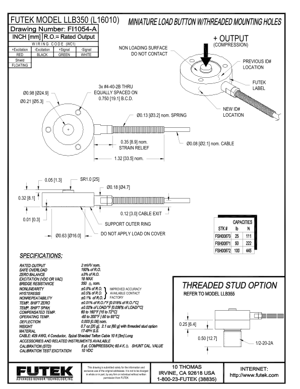
Page 1 Text Content
FUTEK MODEL LLB350 (L16010)
+ OUTPUT
W I R I N G C O D E (WC1) (COMPRESSION)
NON LOADING SURFACE
+Excitation -Excitation +Signal -Signal
RED BLACK GREEN WHITE DO NOT CONTACT
Shield
PREVIOUS ID#
FLOATING
LOCATION
FUTEK
3x #4-40-2B THRU
LABEL
Ø0.98 [Ø24.9] EQUALLY SPACED ON 0.750 [19.1] B.C.D.
NEW ID# Ø0.13 [Ø3.2] nom. SPRING LOCATION
0.35 [8.9] nom.
Ø0.08 [Ø2.1] nom. CABLE
STRAIN RELIEF
1.32 [33.5] nom.
0.05 [1.3] SR1.0 [25]
0.12 [3.0] CABLE EXIT
SUPPORT OUTER RING DO NOT APPLY LOAD ON COVER
IMPROVED ACCURACY AVAILABLE CONTACT FACTORY
This drawing is submitted solely for the information and exclusive use of the original addressee. It is not to be divulged in whole or in part, by any firm or individual without written
permission from FUTEK
Page Summary Contents For FUTEK MODEL LLB350 (L16010) Data Sheet
Manual Details
| Brand | FUTEK |
|---|---|
| Pages | 1 |
| File Size | 153.40 KB |
| Published | May 21, 2026 |
Enter the captcha to get the download link:

Frequently Asked Questions
What specific wires are connected to the output wiring code (WC1)?
The connections include Excitation, +Signal, -Signal, and Shield cables.
Can this product be used on surfaces that bear weight?
No, it is designated for Non Loading Surface use only.
What do the listed threads refer to on the mounting hardware?
There are three #4-40-2B threads located on the label, equally spaced around the device.
Where should the electrical cables exit the unit?
The cable exits are specified with dimensions and include a support outer ring for the connection.