FUTEK LCF700 Handbook/Instructions/User Guide
Summary
Comprehensive technical specification sheet for the FUTEK LCF700 industrial model. This detailed drawing outlines precise dimensions, wiring codes, mounting configurations, and crucial connection points including dual bridge receptacles. Essential for engineers, technicians, and industrial buyers who require accurate guidance for integrating or maintaining complex tensioning and sensing hardware. Use this guide to ensure correct component assembly and electrical connection compliance.
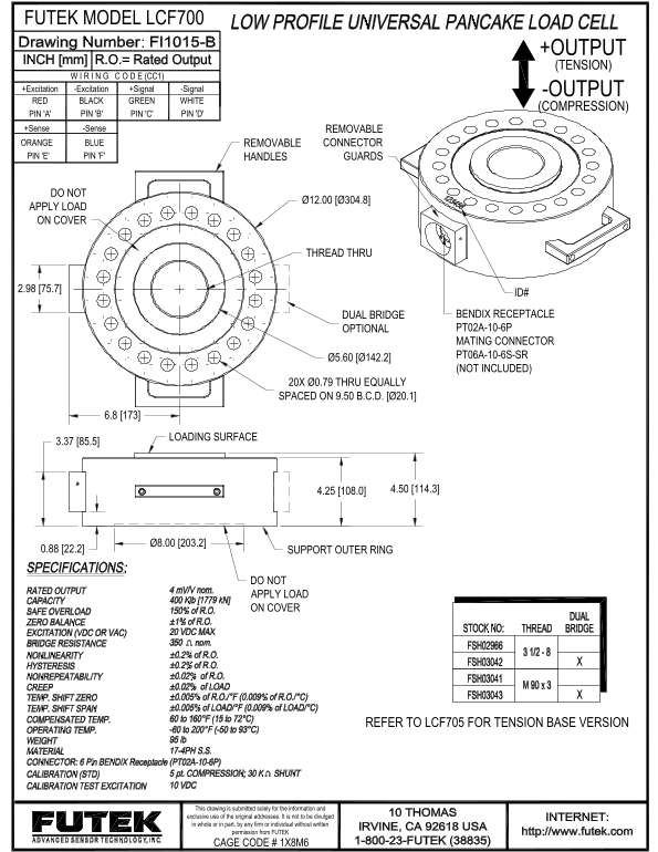
Page 1 Text Content
FUTEK MODEL LCF700
+OUTPUT (TENSION)
W I R I N G C O D E (CC1)
+Excitation +Signal-Excitation -Signal -OUTPUT
BLACKRED GREEN WHITE
(COMPRESSION)
PIN 'A' PIN 'B' PIN 'D'PIN 'C'
+Sense -Sense REMOVABLE ORANGE BLUE REMOVABLE CONNECTOR
PIN 'E' PIN 'F' HANDLES GUARDS
DO NOT
APPLY LOAD ON COVER
THREAD THRU
DUAL BRIDGE BENDIX RECEPTACLE OPTIONAL PT02A-10-6P MATING CONNECTOR PT06A-10-6S-SR
(NOT INCLUDED)
20X Ø0.79 THRU EQUALLY SPACED ON 9.50 B.C.D. [Ø20.1]
LOADING SURFACE
0.88 [22.2] SUPPORT OUTER RING
DO NOT APPLY LOAD ON COVER
REFER TO LCF705 FOR TENSION BASE VERSION
This drawing is submitted solely for the information and exclusive use of the original addressee. It is not to be divulged in whole or in part, by any firm or individual without written
permission from FUTEK CAGE CODE # 1X8M6
Page Summary Contents For FUTEK LCF700 Handbook/Instructions/User Guide
Manual Details
| Brand | FUTEK |
|---|---|
| Pages | 1 |
| File Size | 131.99 KB |
| Published | May 21, 2026 |
Enter the captcha to get the download link:

Frequently Asked Questions
What areas must not have load applied to them?
Do not apply load on the cover or the support outer ring.
Which pins handle the main signals and excitation wiring?
Excitation uses dedicated + and - lines, while Signal uses its own separate + and - lines. The main output is handled by RED, BLACK, GREEN, and WHITE wires.
How can I find documentation for a tension base version?
Refer to the LCF705 manual or drawing for detailed information on the tension base version.
What are the removable connection components?
The orange and blue connectors are removable. An optional mating connector (PT06A-10-6S-SR) is also available.