EXTECH Dual Input Thermometer 421509 - NIST Certificate 153117 117V AC Adaptor User Manual (Part 1) Owner's Manual
Summary
Monitor critical controlled environments using this comprehensive datalogging system designed for recording temperature and relative humidity in facilities such as greenhouses, warehouses, and food transports. The accompanying manual provides detailed guidance on both hardware operation and software usage (Model SW276). It covers everything from initial setup and reading monitoring to setting alarm limits, data retrieval via PC, and proper battery replacement. This kit is essential for professionals requiring accurate, sustained environmental data logging in regulated industrial settings.
Page 1 Text Content
User Guide
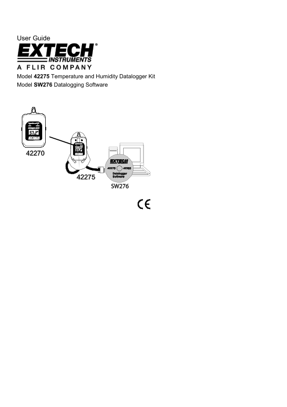
Model Temperature and Humidity Datalogger Kit Model SW276 Datalogging Software
Page Summary Contents For EXTECH Dual Input Thermometer 421509 - NIST Certificate 153117 117V AC Adaptor User Manual (Part 1) Owner's Manual
Page 1
User Guide Model Temperature and Humidity Datalogger Kit Model SW276 Datalogging Software
Page 2
Introduction Congratulations on your purchase of Extech Instrument’s Datalogging instrumentation and software. This User Guide serves two purposes, refer to the list below: 1. This User Guide covers t...
Page 3
Displays LCD Display REC: Displayed while logging readings. Read the ‘Recording Status’ section for further details. HI and LOW: Displayed when the High or Low Alarm limit is exceeded. See ‘Alarm Stat...
Page 4
Software Operation Main Screen Diagram A: Main Screen Cursor and Control Click on cursor line to select it. When the red cursor line is clicked, it turns bold red. When you click the green cursor, it ...
Page 5
Zoom and Pan on Graphs To zoom in, press the <Ctrl> key and click the mouse button over the desired point; release the <Ctrl> key after the mouse button is pressed. The view resolution inc...
Page 6
Retrieve File Click on RETRIEVE FILE to retrieve previously saved file. To aid in reading graph, grid can be drawn on the graph. dialogue box at the hand corner shows the grid (CONTROL LOCATION Cursor...
Page 7
Com Port Setup Select "Com. Set". Select the COM port, Baud rate (9600), Data bits (8), Parity (None) and Stop bits (1). Select OK to accept settings, press Cancel to abort and exit. 42275-E...
Page 8
Datalogger Settings Press LOGGER to access the menu page Sample Rate Setup Number of Data Points Select the desired number of data samples to log: 4000/ 16000. Scroll up or down to located the value a...
Page 9
Start Mode Setup Datalogger Clock Setting Click OK to set logger to PC system time. Alarm Setting The default High Alarm temperature is The default Low Alarm temperature is -40 The default High Alarm ...
Page 10
Unit Setting Temperature can be displayed in "C" or "F" Data Logger ID Setting The datalogger's ID setting allows the user to provide unique name for each datalogger (up to 8-digit...
Page 11
Data Table Press the DATA TABLE icon to view data GO Process the data using the conditions selected. Channel Selects Temperature or Humidity for analysis. Condition Selects if range values are “AND” (...
Page 12
Statistics Press the STATISTICS icon to view histograms of data based on the "Whole Range" or the "Cursor Range". See (Diagram I) Whole Range All of the logged readings. Cursor Ran...
Page 13
4. Diagram I-2 is another example of setting the cursor range; it has been set to divisions. 5. Diagram J-1 shows that cursor is used for the temperature readings and the lower region shows the Relati...
Page 14
Group Files Click GROUP FILES to view the "Multi-Logger Monitor" designed to view and compare data files. Diagram shows the screen as it appears before the icon is clicked. Select the color ...
Page 15
Click to select the file that will be used for comparison, click the color icon box to select the desired color. Each file is represented by capital letter (A through H) with the file name following t...
Page 16
Previous Setting Previous setting records are listed in this column for reference. To download data from another datalogger without exiting the current screen: a) Click “PREVIOUS SETTING" to repl...
Page 17
Message The message area is blank if no file has been retrieved. After file is retrieved the message will display as follows: "Retrieve file completed" Download Commands Start To begin downl...
Page 18
Example 2: Set the Offset to "4000" (refer to Diagram and S1). The screen shows as the starting point for the 8,000 record total. Display Control (for X-Axis records) Range Allows the user t...
Page 19
Example 1: Set the Range by clicking dragging the red indicator (Diagram T) to "1K" (Diagram T-1 shows data records from to 1000). Example 2: Set the Range to "4K" as in Diagram U....
Page 20
Battery Replacement Follow these steps to remove and replace the battery: 1. Remove the four (4) rear Phillips-head screws 2. Ensure that the o-ring remains in its groove. 3. Remove the expired batter...
Manual Details
| Brand | Dual |
|---|---|
| Pages | 20 |
| File Size | 1.20 MB |
| Published | May 31, 2026 |
74 views
Enter the captcha to get the download link:
