EXTECH 400A AC DC Current Clamp-on MultiMeter Adaptor User Guide
Summary
Measure high-amperage AC/DC currents up to 400A using this professional clamp-on adaptor designed for multimeters. This comprehensive guide provides clear instructions on setup, ideal connectivity details, precise technical specifications, and critical electrical safety warnings. It is an essential tool and manual resource for electricians, maintenance personnel, and technicians requiring reliable, high-capacity testing solutions.
Page 1 Text Content
User’s Guide Model CA250 400A AC/DC Current Clamp-on Multi Meter Adaptor
Introduction Current Measurements
1. Set the DMM to the AC or DC m V range or to the lowest voltage
Congratulations on your purchase of the
Extech CA250 400 Amp AC/DC Clamp- range. On Multi Meter Adaptor. With this clamp 2. Connect the RED test lead to the DMM '+' Voltage terminal and adaptor, a current can be measured by the BLACK lead to the '-' COM terminal.
simply clamping around a single 3. Set the adaptor to the 40A (AC or DC) or the 400A (AC or DC) conductor. The adaptor outputs an m V
range.
signal that is proportional to the
4. Press the Jaw Trigger to open the jaw and clamp around a single
measured current and displayed on a
conductor.
DMM. Careful use of this device will provide years of reliable service.
5. The unit will output an AC or DC voltage proportional to the Specifications measured current. (40A range:10m V/A, 400A range:1m V/A) 6. Read the voltage on the DMM display and interpret as
Measurement Ranges 0 to 40 Amps AC/DC current.(direct m V to A on the 400A range, divide by 10 on the
0 to 400 Amps AC/DC 40A range)
Adaptor Output 10m V/Amp on the 0 to 40A range
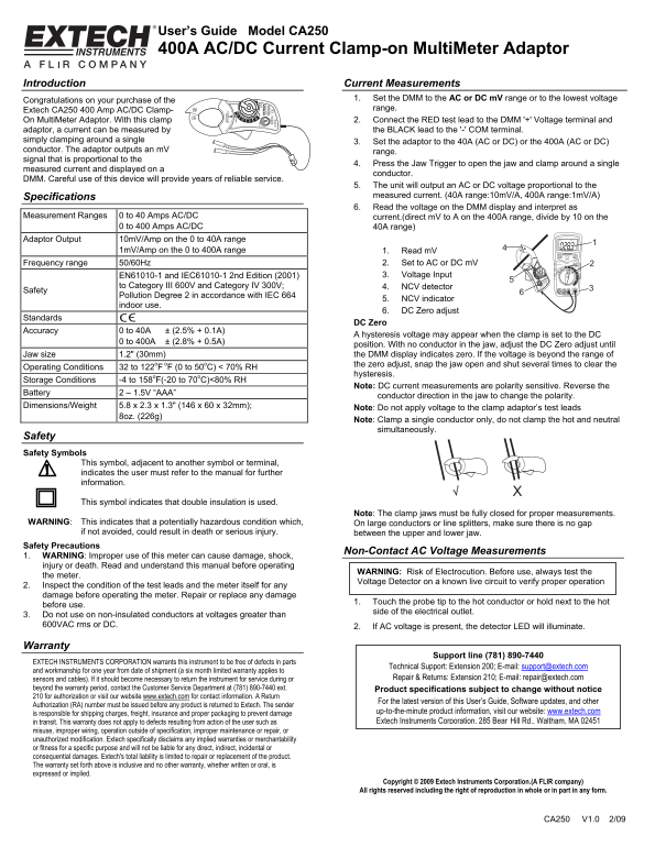
1m V/Amp on the 0 to 400A range 1. Read m V
Frequency range 50/60Hz 2. Set to AC or DC m V EN61010-1 and IEC61010-1 2nd Edition (2001) 3. Voltage Input
to Category III 600V and Category IV 300V; 4. NCV detector
Safety
Pollution Degree 2 in accordance with IEC 664
5. NCV indicator
indoor use.
6. DC Zero adjust
Standards CC
DC Zero
Accuracy 0 to 40A ± (2.5% + 0.1A)
A hysteresis voltage may appear when the clamp is set to the DC
0 to 400A ± (2.8% + 0.5A)
position. With no conductor in the jaw, adjust the DC Zero adjust until Jaw size 1.2" (30mm) the DMM display indicates zero. If the voltage is beyond the range of the zero adjust, snap the jaw open and shut several times to clear the
Operating Conditions 32 to 122o F o F (0 to 50o C) < 70% RH
hysteresis.
Storage Conditions -4 to 158o F(-20 to 70o C)<80% RH
Note: DC current measurements are polarity sensitive. Reverse the
Battery 2 – 1.5V “AAA”
conductor direction in the jaw to change the polarity.
Dimensions/Weight 5.8 x 2.3 x 1.3" (146 x 60 x 32mm);
Note: Do not apply voltage to the clamp adaptor’s test leads
8oz. (226g)
Note: Clamp a single conductor only, do not clamp the hot and neutral simultaneously.
Safety Safety Symbols
This symbol, adjacent to another symbol or terminal, indicates the user must refer to the manual for further information.
This symbol indicates that double insulation is used.
Note: The clamp jaws must be fully closed for proper measurements.
WARNING: This indicates that a potentially hazardous condition which, On large conductors or line splitters, make sure there is no gap
if not avoided, could result in death or serious injury. between the upper and lower jaw.
Safety Precautions
Non-Contact AC Voltage Measurements
1. WARNING: Improper use of this meter can cause damage, shock, injury or death. Read and understand this manual before operating
WARNING: Risk of Electrocution. Before use, always test the
the meter.
Voltage Detector on a known live circuit to verify proper operation
2. Inspect the condition of the test leads and the meter itself for any damage before operating the meter. Repair or replace any damage
1. Touch the probe tip to the hot conductor or hold next to the hot
before use.
side of the electrical outlet.
3. Do not use on non-insulated conductors at voltages greater than 600VAC rms or DC. 2. If AC voltage is present, the detector LED will illuminate.
Warranty
Support line (781) 890-7440
EXTECH INSTRUMENTS CORPORATION warrants this instrument to be free of defects in parts
Technical Support: Extension 200; E-mail: [email protected]
and workmanship for one year from date of shipment (a six month limited warranty applies to
sensors and cables). If it should become necessary to return the instrument for service during or Repair & Returns: Extension 210; E-mail: [email protected]
beyond the warranty period, contact the Customer Service Department at (781) 890-7440 ext. Product specifications subject to change without notice 210 for authorization or visit our website www.extech.com for contact information. A Return
For the latest version of this User’s Guide, Software updates, and other
Authorization (RA) number must be issued before any product is returned to Extech. The sender
is responsible for shipping charges, freight, insurance and proper packaging to prevent damage up-to-the-minute product information, visit our website: www.extech.com in transit. This warranty does not apply to defects resulting from action of the user such as Extech Instruments Corporation, 285 Bear Hill Rd., Waltham, MA 02451
misuse, improper wiring, operation outside of specification, improper maintenance or repair, or unauthorized modification. Extech specifically disclaims any implied warranties or merchantability or fitness for a specific purpose and will not be liable for any direct, indirect, incidental or consequential damages. Extech's total liability is limited to repair or replacement of the product. The warranty set forth above is inclusive and no other warranty, whether written or oral, is expressed or implied.
Copyright © 2009 Extech Instruments Corporation.(A FLIR company) All rights reserved including the right of reproduction in whole or in part in any form.
CA250 V1.0 2/09
Page Summary Contents For EXTECH 400A AC DC Current Clamp-on MultiMeter Adaptor User Guide
Manual Details
| Brand | Current |
|---|---|
| Pages | 1 |
| File Size | 98.12 KB |
| Published | May 18, 2026 |
Enter the captcha to get the download link:

Frequently Asked Questions
What is the maximum current range available on this adaptor?
It measures up to both 40 Amps and 400 Amps AC/DC.
What must I check before operating the meter?
You must inspect the test leads and the meter itself for any damage, and always verify the voltage detector on a known live circuit.
How do I perform the DC Zero adjustment?
Snap the jaw open and shut several times with no conductor in the jaws until the DMM display indicates zero.