LEM DRH-AC10 AC DC Current Transducer Data Handbook User Manual
Summary
Accurately measure extremely challenging electrical environments with this high-power AC/DC current transducer. Featuring True RMS technology and built-in galvanic isolation, the device precisely senses distorted waveforms for loads ranging from VFDs to ballasts, providing a reliable 0-10V analog output signal. This manual serves as the complete technical guide for professionals, engineers, and technicians requiring detailed performance parameters, electrical data, installation guidelines, and crucial safety information for seamless system integration in industrial settings.
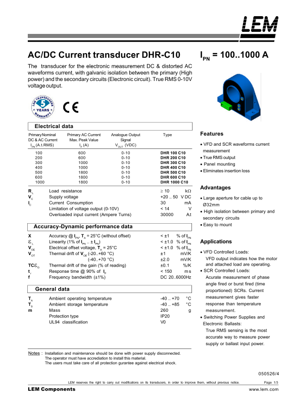
Page 1 Text Content
AC/DC Current transducer DHR-C10 IPN = 100..1000 A
The transducer for the electronic measurement DC & distorted AC waveforms current, with galvanic isolation between the primary (High power) and the secondary circuits (Electronic circuit). True RMS 0-10V voltage output.
Electrical data
Primary Nominal Primary AC Current Analogue Output Type Features
DC & AC Current Max. Peak Value Signal
IPN (A.t.RMS) IP (A) VOUT (VDC) • VFD and SCR waveforms current measurement
0-10 DHR 100 C10
0-10 DHR 200 C10 • True RMS output
0-10 DHR 300 C10
• Panel mounting
0-10 DHR 400 C10
• Eliminates insertion loss
0-10 DHR 500 C10 0-10 DHR 600 C10 0-10 DHR 1000 C10
Advantages
R L Load resistance ≥ 10 kΩ VC Supply voltage +20 .. 50 V DC
• Large aperture for cable up to
IC Current Consumption m A
Ø32mm
Limitation of voltage output (0-10V) < 14
• High isolation between primary and
Overloaded input current (Ampere Turns) A.t
secondary circuits • Easy to mount
Accuracy-Dynamic performance data Accuracy @ IPN, TA = 25°C (without offset) < ±1 % of IPN
Linearity (1% of IPN .. ± IPN) < ±1.0 % of IPN Applications
VOE Electrical offset voltage, TA = 25°C < ±1.0 % of IPN
• VFD Controlled Loads:
VOT Thermal drift of VOE (-20..+60 °C) ±1 m V/K
(-40..+70 °C) ±2.0 m V/K VFD output indicates how the motor TCεG Thermal drift of the gain (% of reading) ±0.1 %/K and attached load are operating. t r Response time @ 90% of IP < 150 • SCR Controlled Loads:
Frequency bandwidth (±1%) DC 20..6000Hz Acurate measurement of phase
angle fired or burst fired (time
General data
proportioned) SCRs. Current measurement gives faster
TA Ambient operating temperature -40 .. +70 °C
TS Ambient storage temperature -40 .. +85 °C response than temperature
Mass measurement. Protection type IP20 • Switching Power Supplies and UL94 classification V0
Electronic Ballasts: True RMS sensing is the most accurate way to measure power supply or ballast input power.
Notes : Installation and maintenance should be done with power supply disconnected. The operator must have accrediation to install this material. The users must take care of all protection gurantee against electrical shock.
LEM reserves the right to carry out modifications on its transducers, in order to improve them, without previous notice. Page 1/3
LEM Components www.lem.com
Page Summary Contents For LEM DRH-AC10 AC DC Current Transducer Data Handbook User Manual
Manual Details
| Brand | Current |
|---|---|
| Pages | 3 |
| File Size | 72.99 KB |
| Published | June 03, 2026 |
Enter the captcha to get the download link:

Frequently Asked Questions
How do I properly install the DHR-C10 panel?
The manual advises using new M4 screws appropriate for your panel's thickness and noting that connections should only be made after disconnecting the power supply.
Are there electrical safety precautions required when operating this transducer?
Yes. Always treat the unit with caution regarding electric shock risk, as parts like the primary busbar carry hazardous voltage. The main supply must be disconnected for maintenance.
What is the guaranteed accuracy measurement capability of the device?
The accuracy at I, T = 25°C (without offset) is specified to be less than ±1% of I.
What types of electrical loads can this transducer measure?
It supports measurement of both VFD Controlled Loads and SCR Controlled Loads. It also measures power supply or ballast input power with True RMS sensing.