Page 1
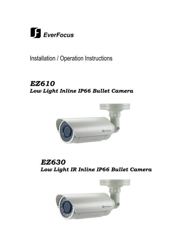
Ever Focus Installation / Operation Instructions EZ610 Low Light Inline IP66 Bullet Camera EZ630 Low Light IR Inline IP66 Bullet Camera
Page 2
EVERFOCUS LECTRONI CORPORAT ION P/N: 4605XZ0610004AR Operation Instruction 2010 Ever Focus Electronics Corp Please read this manual first for correct installation and operation. This manual should b...
Page 3
Precautions 1. Do not install the camera near electric or magnetic fields. Install the camera away from TV/radio transmitters, magnets, electric motors, transformers and audio speakers since the elect...
Page 4
Federal Communication Commission Interference Statement This equipment has been tested and found to comply with the limits for a Class A digital device, pursuant to Part 15 of the FCC Rules. These lim...
Page 5
Table of Contents 1 Product Overview..............................................................................................................................................7 1.1 Features ..........
Page 6
4 RS-485 Remote Control ..................................................................................................................................31 4.1 Remote control with EKB-500 keyboard......
Page 7
Chapter 1 PRODUCT OVERVIEW Amazing color low light sensitivity of 0.05 lux before the added benefits of advanced DSP technology, delivered by a 1/3” Sony Super HAD II sensor, is just the beginning wit...
Page 8
• IP66 weather resistant • Dual voltage (12VDC/24VAC) with line lock to AC supply 1.2 Accessory Parts List Please be careful when you unpack the box and the electronic device inside. Check and make su...
Page 9
1.3 Specifications Model EZ610 EZ630 Pickup Device 1/3" SONY Super HAD II CCD Video Format NTSC, PAL (by model) Picture Elements 768 x 494(NTSC)/ 752 x 582 (PAL) Horizontal Resolution 560 TVL Sen...
Page 10
Weight 1250 g / 2.275 lbs. Mounting Pattern Speedy-Mount Ring mates with 4” round electrical box; base swivel is 1” NPT – remove base plate for coupling to standard conduit fittings. Certifications CE...
Page 11
1.5 Camera Component Description Speedy-mount Ring Sunshield Use a coin or screwdriver to remove the cover Controls are inside the cover Red: Menu mode Green: Lens mode 1) Reset: To load the factory d...
Page 12
1.6 Related Products In addition, you may order the following Ever Focus products which are recommended for use with the camera to achieve the best performance: • Ever Focus control keyboard (EKB500) ...
Page 13
Chapter 2 INSTALLATION This chapter will describe, in general terms, how to install the EZ610/630 camera. STEPS: 1. Wire and mount the camera. See 2.1 2. Adjust the camera position. See 2.2 Warning To...
Page 14
Video & Power cables RS485 cable (optional) White: RS-485 + Black: RS-485 - Power Socket RS-485 cable Connect the power and video cables. Attach the camera to the speedy-mount ring, securing it wi...
Page 15
2.2 Adjust Camera Position Adjust the viewing angle to the desired direction. With this unique 3-axis positioning system, installers can capture images from virtually any angle, without compromising. ...
Page 16
3rd axis Loosen lock ring and set screw to rotate camera 360° Sunshield To remove or install the sunshield, use the hexagon wrench provided to loosen the screw at sunshield. Loosen this screw Slide ri...
Page 17
Note: When properly installed, the rear of the sunshield is even with the rear of the camera body; improperly extending the sunshield to ‘shade’ the lens can compromise image quality, particularly on ...
Page 18
Chapter 3 OSD MENU SETUP This chapter introduces how to change RS485 ID and Baud Rate and to configure the camera OSD menu. STEPS If you want to connect to the camera with a keyboard or other RS-485 -...
Page 19
NOTE: For those selected items with “ ” sign in the end, there is a sub-menu for further settings. Return to Previous Page Go to “Return” by turning the mini-joystick and press the mini-joystick to re...
Page 20
3.3 OSD Menu Setup 3.3.1 OSD Menu Tree Default settings are shown bold or in brackets. Lens — DC — Brightness 0~100 (50) Exposure — Shutter — x256, x128, x64, x32, x16, x8, x4, x2, 1/60(NTSC) / 1/50 (...
Page 21
— Motion — Off — On — Area Select — Area1-Area4 — Area Display — Off, On — Left/Right — 5~66 — Width — 0~93 — Top/Bottom — 1~60 — Height — 0~60 — Sensitivity — 0~40 — Motion View — Off, On — Return — ...
Page 22
3.3.3 EXPOSURE 3.3.3.1 SHUTTER 1. When the SETUP menu is displayed on the screen, please direct the arrow to point to “EXPOSURE” -> “SHUTTER” by using the UP and DOWN buttons. 2. Select the shutter...
Page 23
3.3.3.4 BLC-Backlight Compensation There are three choices for the type of BLC which may be employed: OFF, traditional BLC or HSBLC. BLC Video gain can be adjusted automatically to correct the exposur...
Page 24
TOP/BOTTOM Set the Top/Bottom side of an area for the HSBLC to be adjusted. The value adjustable is 0~6. HEIGHT Set the height of an area for the HSBLC to be adjusted. The value adjustable is 0~6. RET...
Page 25
MANUAL The manual adjustment mode enables a more precise adjustment. Please select ATW or AWC first. Then change to manual adjustment mode and press the SETUP button. Set the suitable color temperatur...
Page 26
EXT The picture will switch automatically to color in a normal environment and to B/W when the ambient illumination is low based on the illumination reaching the light sensor at the front of the camer...
Page 27
3.3.7.2 D-EFFECT Offers a number of digital functions for processing the image. 3.3.7.3 FREEZE OFF Select “OFF” to view live image. ON Select “ON” to freeze and display current live image. 3.3.7.4 MIR...
Page 28
3.3.7.6 GAMMA This menu allows adjustment of gamma correction for ideal linearity of image brightness and contrast in the range 0.05 to 1.0. 3.3.7.7 NEG. IMAGE Allows user to create a negative of the ...
Page 29
SELECT mode. AREA DISPLAY Select “ON” to use the area selected in the AREA SELECT. Select “OFF” to disable this function. LEFT/RIGHT Set the coordinate of the horizontal axis 6~98. WIDTH Set the size ...
Page 30
3.3.8.3 RED Adjust image’s red level. The available range of level is 0~100. Press “RET” to saves all settings in the ADJUST menu and returns to the previous menu. Press “END” to save all the menu set...
Page 31
Chapter 4 RS-485 REMOTE CONTROL 4.1 Remote control with EKB-500 keyboard 4.1.1 RS - 485 Wiring For more details about RS-485 wiring please consult related chapters in EKB-500 user manual. Note! Before...
Page 32
SETUP 1. LENS DC <┘ 2. EXPOSURE <┘ 3. WHITE BAL. AWB d. Move the joystick RIGHT (�) and LEFT (�) to adjust the mode and parameters of the selected item. Press “Menu” to leave and goes to previou...
Page 33
Ever Focus Electronics Corp. Headquarters Office Beijing office 12F, No.79 Sec.1 Shin-Tai Wu Road, Room 609,Technology Trade Building. Hsi-Chi, Taipei, Taiwan Shangdi Information Industry Base, Tel: +...