Data Handbook for Fairchild 6N137 HCPL-2630 HCPL-2601 HCPL-2631 HCPL-2611
Summary
These high-speed logic gate optocouplers are engineered for reliable signal data transmission and robust electrical isolation, supporting speeds up to 10 MBit/s and offering superior Common Mode Rejection (CMR). Ideal for applications like ground loop elimination, LSTTL to TTL conversion, and computer peripheral interfacing. The accompanying manual provides essential technical specifications, absolute maximum ratings, switching timing parameters, and comprehensive application details necessary for electronics designers integrating high-performance isolation circuitry.
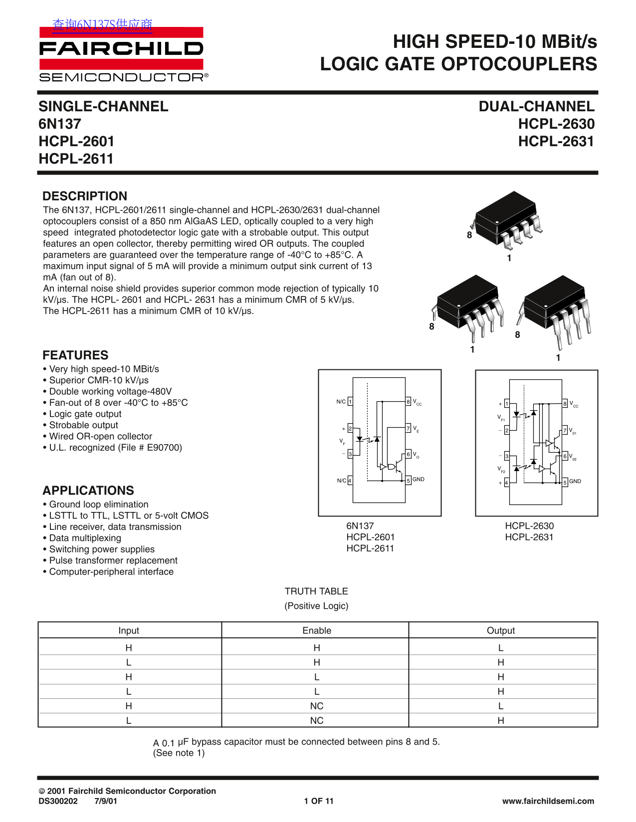
Page 1 Text Content
HIGH SPEED-10 MBit/s LOGIC GATE OPTOCOUPLERS
SINGLE-CHANNEL DUAL-CHANNEL 6N137 HCPL-2630 HCPL-2601 HCPL-2631 HCPL-2611
DESCRIPTION The 6N137, HCPL-2601/2611 single-channel and HCPL-2630/2631 dual-channel optocouplers consist of a 850 nm Al Ga AS LED, optically coupled to a very high speed integrated photodetector logic gate with a strobable output. This output features an open collector, thereby permitting wired OR outputs. The coupled parameters are guaranteed over the temperature range of -40°C to +85°C. A maximum input signal of 5 m A will provide a minimum output sink current of 13 m A (fan out of 8). An internal noise shield provides superior common mode rejection of typically 10 k V/µs. The HCPL- 2601 and HCPL- 2631 has a minimum CMR of 5 k V/µs. The HCPL-2611 has a minimum CMR of 10 k V/µs.
FEATURES • Very high speed-10 MBit/s • Superior CMR-10 k V/µs • Double working voltage-480V
• Fan-out of 8 over -40°C to +85°C 8N/C CC 8+
• Logic gate output
• Strobable output • Wired OR-open collector • U.L. recognized (File # E90700)
N/C GND GND
APPLICATIONS • Ground loop elimination • LSTTL to TTL, LSTTL or 5-volt CMOS
• Line receiver, data transmission 6N137 HCPL-2630 • Data multiplexing HCPL-2601 HCPL-2631 • Switching power supplies HCPL-2611
• Pulse transformer replacement • Computer-peripheral interface
TRUTH TABLE (Positive Logic)
Input Enable Output
NC NC
A 0.1 µF bypass capacitor must be connected between pins 8 and 5. (See note 1)
2001 Fairchild Semiconductor Corporation DS300202 7/9/01 1 OF 11 www.fairchildsemi.com
Page Summary Contents For Data Handbook for Fairchild 6N137 HCPL-2630 HCPL-2601 HCPL-2631 HCPL-2611
Manual Details
| Brand | Fairchild |
|---|---|
| Pages | 11 |
| File Size | 203.68 KB |
| Published | July 07, 2026 |
Enter the captcha to get the download link:

Frequently Asked Questions
What specific conditions govern the electrical parameters over temperature?
The coupled parameters are guaranteed over a wide operating temperature range of -40°C to +85°C.
Does this optocoupler require an external bypass capacitor for operation?
Yes, a 0.1 µF bypass capacitor must be connected between pins 8 and 5.
What is the maximum guaranteed fan-out capability?
The component supports a fan-out of 8 over the specified temperature range.
Are these couplers suitable for use in life support devices?
No, they are not authorized for use as critical components in life support systems without express written approval.