# A B C D E F G H I J K L M N O P Q R S T U V W X Y Z

HP HCPL-4504 HCPL-0454 HCNW4504 Data Manual

Summary

Texas Instruments semiconductor datasheet covering features, pin diagrams, functional block description, electrical specifications, timing characteristics, application information, power supply requirements, and package mechanical drawings.
📄 Preview PAGE OF 16

Page 1 Text Content

查询HCNW4504供应商

High CMR, High Speed Optocouplers

Technical Data

HCPL-4504 HCPL-0454 HCNW4504

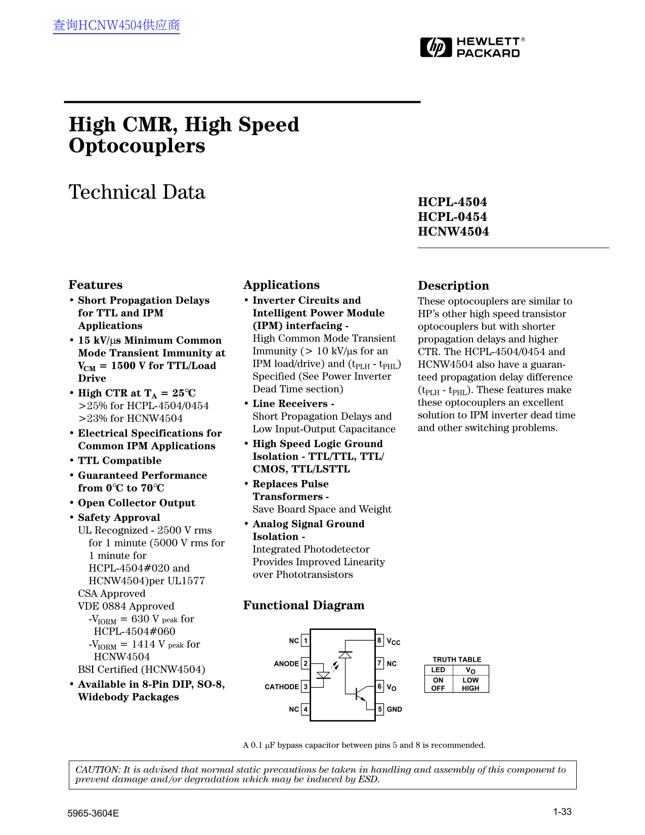
Features Applications Description • Short Propagation Delays • Inverter Circuits and These optocouplers are similar to for TTL and IPM Intelligent Power Module HP’s other high speed transistor Applications (IPM) interfacing - optocouplers but with shorter

• 15 k V/µs Minimum Common High Common Mode Transient propagation delays and higher Mode Transient Immunity at Immunity (> 10 k V/µs for an CTR. The HCPL-4504/0454 and VCM = 1500 V for TTL/Load IPM load/drive) and (t PLH - t PHL) HCNW4504 also have a guaran- Drive Specified (See Power Inverter teed propagation delay difference Dead Time section) (t PLH - t PHL). These features make

• High CTR at TA = 25°C

• Line Receivers - these optocouplers an excellent

>25% for HCPL-4504/0454

Short Propagation Delays and solution to IPM inverter dead time

>23% for HCNW4504

Low Input-Output Capacitance and other switching problems.

• Electrical Specifications for

Common IPM Applications • High Speed Logic Ground Isolation - TTL/TTL, TTL/

• TTL Compatible

CMOS, TTL/LSTTL

• Guaranteed Performance

• Replaces Pulse

from 0°C to 70°C

Transformers

• Open Collector Output

Save Board Space and Weight

• Safety Approval

• Analog Signal Ground

UL Recognized - 2500 V rms

Isolation -

for 1 minute (5000 V rms for

Integrated Photodetector

1 minute for

Provides Improved Linearity

HCPL-4504#020 and

over Phototransistors

HCNW4504)per UL1577 CSA Approved

VDE 0884 Approved Functional Diagram

-VIORM = 630 V peak for HCPL-4504#060

8NC VCC

-VIORM = 1414 V peak for HCNW4504 TRUTH TABLE

ANODE NC

BSI Certified (HCNW4504) LED VO

ON LOW

• Available in 8-Pin DIP, SO-8, CATHODE VO

OFF HIGH

Widebody Packages

NC GND

A 0.1 µF bypass capacitor between pins 5 and 8 is recommended.

CAUTION: It is advised that normal static precautions be taken in handling and assembly of this component to prevent damage and/or degradation which may be induced by ESD.

Page Summary Contents For HP HCPL-4504 HCPL-0454 HCNW4504 Data Manual

Page 1 查询HCNW4504供应商 High CMR, High Speed Optocouplers Technical Data HCPL-4504 HCPL-0454 HCNW4504 Features Applications Description • Short Propagation Delays • Inverter Circuits and These optocouplers are ...
Page 2 The HCPL-4504/0454 and These single channel, diode- the photodiode bias and output- HCNW4504 CTR, propagation transistor optocouplers are transistor collector increase the delay, and CMR are specified...
Page 3 Package Outline Drawings 8-Pin DIP Package (HCPL-4504) TYPE NUMBER 6.35 ± 0.25 OPTION CODE* HP XXXXZ DATE CODE YYWW UR UL RECOGNITION 1.78 (0.070) MAX. 1.19 (0.047) MAX. 5° TYP. - 0.051 4.70 (0.185) M...
Page 4 Small Outline SO-8 Package (HCPL-0454) YWW TYPE NUMBER (0.155 ± 0.005) (LAST 3 DIGITS) DATE CODE (0.016 ± 0.003) 1.270 BSG (0.050) 0.305 MIN.DIMENSIONS IN MILLIMETERS (INCHES). LEAD COPLANARITY = 0.10...
Page 5 8-Pin Widebody DIP Package with Gull Wing Surface Mount Option 300 (HCNW4504) 11.15 ± 0.15 (0.442 ± 0.006) PAD LOCATION (FOR REFERENCE ONLY) 6.15 TYP. (0.242) 11.00 MAX. (0.433) 4.00 MAX. (0.158) BSC ...
Page 6 Regulatory Information CSA BSI The devices contained in this data Approved under CSA Component Certification according to sheet have been approved by the Acceptance Notice #5, File CA BS451:1994, foll...
Page 7 VDE 0884 Insulation Related Characteristics (HCPL-4504 OPTION 060 ONLY) Description Symbol Characteristic Units Installation classification per DIN VDE 0110/1.89, Table 1 for rated mains voltage ≤ 300...
Page 8 Absolute Maximum Ratings Parameter Symbol Device Min. Max. Units Note Storage Temperature TS -55 °C Operating Temperature TA HCPL-4504 -55 °C HCPL-0454 HCNW4504 -55 Average Forward Input Current IF(AV...
Page 9 Electrical Specifications (DC) Over recommended temperature (TA = 0°C to 70°C) unless otherwise specified. See note 12. Parameter Symbol Device Min. Typ.* Max. Units Test Conditions Fig. Note Current ...
Page 10 AC Switching Specifications Over recommended temperature (TA = 0°C to 70°C) unless otherwise specified. Parameter Symbol Min. Typ. Max. Units Test Conditions Fig. Note Propagation 0.2 0.3 TA = 25°C Pu...
Page 11 Package Characteristics Over recommended temperature (TA = 0°C to 25°C) unless otherwise specified. Parameter Sym. Device Min. Typ.* Max. Units Test Conditions Fig. Note Input-Output VISO HCPL-4504 V ...
Page 12 IZ IO HCPL-4504/0454 HCNW4504 V = 5.0 V CC V = 5.0 V CC I = 5 m AF I = 5 m AF IZ IO VO – OUTPUT VOLTAGE – V VO – OUTPUT VOLTAGE – V Figure 1. DC and Pulsed Transfer Characteristics. HCPL-4504/0454 HCN...
Page 13 IZ IO HCPL-4504/0454 HCNW4504 NORMALIZED IF = 16 m A VO = 0.4 V IF = 0 m A 1.0 VCC = 5.0 V VO = VCC = 5.0 V TA = 25°C NORMALIZED IF = 16 m A 0.95 0.8 VO = 0.4 V VCC = 5.0 V TA = 25°C IZ IO TA – TEMPER...
Page 14 tp IO tp IO tp IO HCPL-4504/0454 HCNW4504 0.50 0.50 1.4 VCC = 5.0 V VCC = 5.0 V VCC = 5.0 V RL = 1.9 kΩ TA = 25° C 0.45 0.45 RL = 1.9 kΩ 1.2 CL = 15 p F CL = 15 p F CL = 15 p F 0.40 VTHHL = VTHLH = 1....
Page 15 HCPL-4504 OPTION 060 PS (m W) IS (m A) HCPL-4504/0454 HCNW4504 LED 1 BASE/GATE DRIVE CIRCUIT OUT 1 HCPL-4504/0454 TS – CASE TEMPERATURE – °C HCNW4504 HCNW4504 LED 2 PS (m W) BASE/GATE IS (m A) DRIVE C...
Page 16 conduct at the same time. transistor turns off when the time is the sum of the maximum Extremely large currents will flow optocoupler LED turns on; this difference in turn-on delay plus if there is an...

Manual Details

Brand HP
Pages 16
File Size 206.88 KB
Published June 22, 2026
9 views

Enter the captcha to get the download link:

captcha

Frequently Asked Questions

What are the electrical safety ratings for these optocouplers?

They are UL Recognized for 2500 V rms isolation for 1 minute, and they also carry CSA Approved and VDE 0884 approvals.

How do these models help with IPM inverters?

Their short propagation delays and high Common Mode Transient Immunity (CMR) offer an excellent solution to minimize dead time during IPM inverter operation.

What precautions must be taken when using or handling this component?

It is advised that normal static precautions be taken during handling and assembly to prevent damage or degradation caused by ESD.