Data Handbook for Fairchild FAN3223 to FAN3225
Summary
These dual 4A, high-speed low-side gate drivers are designed for controlling N-channel MOSFETs in demanding switching applications. Available in three versions (inverting, non-inverting, and dual-input) and supporting both TTL or CMOS logic levels, the device provides exceptional current capability and fast transition times via MillerDrive™ technology. The manual details optimal usage for switch-mode power supplies, synchronous rectifiers, high-efficiency MOSFET switching, and motor control systems.
Page 1 Text Content
3223 / F 24 / F 3225 — al 4A ig -S eed , L -S id e G ate D rivers
July 2012
FAN3223 / FAN3224 / FAN3225 Dual 4A High-Speed, Low-Side Gate Drivers
Features
Description
Industry-Standard Pinouts
The FAN3223-25 family of dual 4A gate drivers is
4.5 to 18V Operating Range
designed to drive N-channel enhancement-mode 5A Peak Sink/Source at VDD = 12V MOSFETs in low-side switching applications by providing high peak current pulses during the short
4.3A Sink / 2.8A Source at VOUT = 6V
switching intervals. The driver is available with either
Choice of TTL or CMOS Input Thresholds TTL or CMOS input thresholds. Internal circuitry
provides an under-voltage lockout function by holding
Three Versions of Dual Independent Drivers:
the output LOW until the supply voltage is within the
- Dual Inverting + Enable (FAN3223)
operating range. In addition, the drivers feature matched - Dual Non-Inverting + Enable (FAN3224) internal propagation delays between A and B channels for applications requiring dual gate drives with critical
- Dual-Inputs (FAN3225)
timing, such as synchronous rectifiers. This also
Internal Resistors Turn Driver Off If No Inputs enables connecting two drivers in parallel to effectively
Miller Drive™ Technology double the current capability driving a single MOSFET. 12ns / 9ns Typical Rise/Fall Times with 2.2n F Load The FAN322X drivers incorporate Miller Drive™ architecture for the final output stage. This bipolar-
Typical Propagation Delay Under 20ns Matched
MOSFET combination provides high current during the
within 1ns to the Other Channel
Miller plateau stage of the MOSFET turn-on / turn-off
Double Current Capability by Paralleling Channels process to minimize switching loss, while providing rail-
to-rail voltage swing and reverse current capability.
8-Lead 3x3mm MLP or 8-Lead SOIC Package
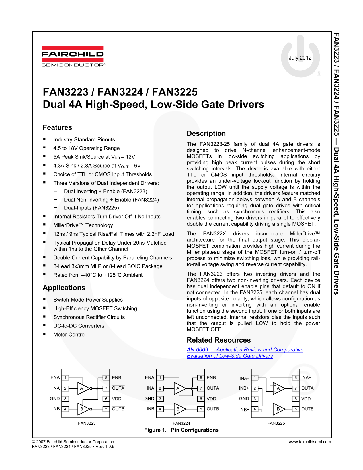
Rated from –40°C to +125°C Ambient The FAN3223 offers two inverting drivers and the FAN3224 offers two non-inverting drivers. Each device has dual independent enable pins that default to ON if
Applications
not connected. In the FAN3225, each channel has dual Switch-Mode Power Supplies inputs of opposite polarity, which allows configuration as non-inverting or inverting with an optional enable
High-Efficiency MOSFET Switching
function using the second input. If one or both inputs are Synchronous Rectifier Circuits left unconnected, internal resistors bias the inputs such that the output is pulled LOW to hold the power
DC-to-DC Converters
MOSFET OFF.
Motor Control
Related Resources AN-6069 — Application Review and Comparative Evaluation of Low-Side Gate Drivers
FAN3223 FAN3224 FAN3225
Figure 1. Pin Configurations
© 2007 Fairchild Semiconductor Corporation www.fairchildsemi.com FAN3223 / FAN3224 / FAN3225 • Rev. 1.0.9
Page Summary Contents For Data Handbook for Fairchild FAN3223 to FAN3225
Manual Details
| Brand | Fairchild |
|---|---|
| Pages | 25 |
| File Size | 1.53 MB |
| Published | July 15, 2026 |
Enter the captcha to get the download link:

Frequently Asked Questions
Which model should I select for non-inverting gate drive applications?
The FAN3224 provides two dedicated non-inverting drivers.
How can I double the total current capability of the driver?
You can connect two devices in parallel using their internal resistors to effectively double the output current.
What is the operating voltage range for this series of gate drivers?
The FAN322X family operates on a wide range from 4.5V to 18V.
If the input control signals are not connected, what safety function activates?
Internal resistors bias the inputs low, pulling the output LOW to ensure the MOSFET remains OFF.