ADuM1400 ADuM1401 ADuM1402 Quad-Channel Digital Isolators Data Sheet Manual
Summary
The ADuM140x family provides advanced, high-speed differential digital isolators for sensitive communication applications. This manual is a comprehensive technical guide for engineers and electronics designers needing reliable galvanic isolation across various power levels (3V to 5.5V) and data rates up to 90 Mbps. It covers detailed electrical characteristics, application examples (RS-485, SPI), operational guidelines, functional block diagrams, and specific ordering information needed to implement robust, noise-immune signal integrity solutions in industrial or general-purpose multichannel systems.
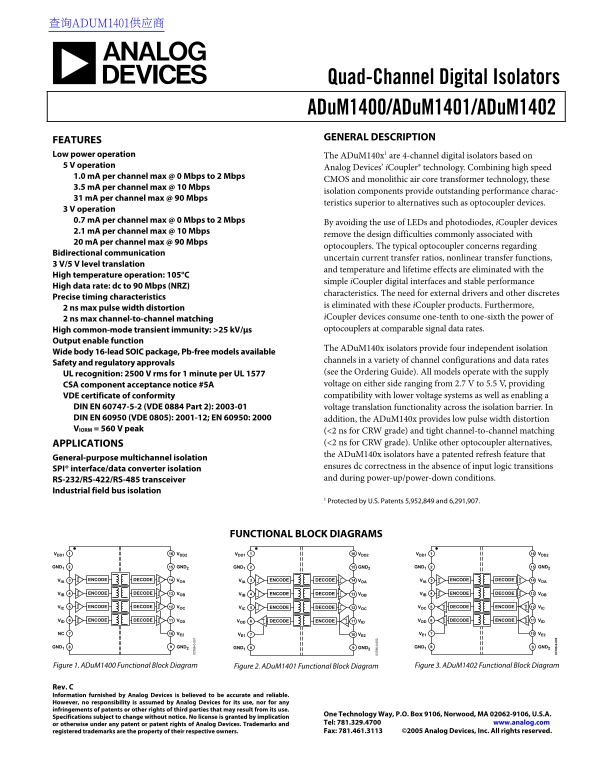
Page 1 Text Content
查询ADUM1401供应商
Quad-Channel Digital Isolators
ADu M1400/ADu M1401/ADu M1402
GENERAL DESCRIPTION
FEATURES Low power operation The ADu M140x1 are 4-channel digital isolators based on 5 V operation
Analog Devices’ i Coupler® technology. Combining high speed
1.0 m A per channel max @ 0 Mbps to 2 Mbps
CMOS and monolithic air core transformer technology, these
3.5 m A per channel max @ 10 Mbps
6- 0- isolation components provide outstanding performance charac-
31 m A per channel max @ 90 Mbps
teristics superior to alternatives such as optocoupler devices.
3 V operation 0.7 m A per channel max @ 0 Mbps to 2 Mbps
By avoiding the use of LEDs and photodiodes, i Coupler devices
2.1 m A per channel max @ 10 Mbps
remove the design difficulties commonly associated with
20 m A per channel max @ 90 Mbps
optocouplers. The typical optocoupler concerns regarding
Bidirectional communication
uncertain current transfer ratios, nonlinear transfer functions,
3 V/5 V level translation
and temperature and lifetime effects are eliminated with the
High temperature operation: 105°C
simple i Coupler digital interfaces and stable performance
High data rate: dc to 90 Mbps (NRZ)
characteristics. The need for external drivers and other discretes
Precise timing characteristics
is eliminated with these i Coupler products. Furthermore,
2 ns max pulse width distortion
2 ns max channel-to-channel matching i Coupler devices consume one-tenth to one-sixth the power of High common-mode transient immunity: >25 k V/μs optocouplers at comparable signal data rates.
Output enable function
The ADu M140x isolators provide four independent isolation
Wide body 16-lead SOIC package, Pb-free models available
channels in a variety of channel configurations and data rates
Safety and regulatory approvals
UL recognition: 2500 V rms for 1 minute per UL 1577 (see the Ordering Guide). All models operate with the supply
CSA component acceptance notice #5A voltage on either side ranging from 2.7 V to 5.5 V, providing VDE certificate of conformity compatibility with lower voltage systems as well as enabling a
DIN EN 60747-5-2 (VDE 0884 Part 2): 2003-01 voltage translation functionality across the isolation barrier. In DIN EN 60950 (VDE 0805): 2001-12; EN 60950: 2000 addition, the ADu M140x provides low pulse width distortion VIORM = 560 V peak (<2 ns for CRW grade) and tight channel-to-channel matching
APPLICATIONS (<2 ns for CRW grade). Unlike other optocoupler alternatives, the ADu M140x isolators have a patented refresh feature that
General-purpose multichannel isolation
ensures dc correctness in the absence of input logic transitions
SPI® interface/data converter isolation
RS-232/RS-422/RS-485 transceiver and during power-up/power-down conditions.
Industrial field bus isolation
1 Protected by U.S. Patents 5,952,849 and 6,291,907.
FUNCTIONAL BLOCK DIAGRAMS
VDD1 6- 0- VDD2 VDD1 VDD2 VDD1 VDD2
GND1 GND2 GND1 GND2 GND1 GND2
VIA ENCODE DECODE VOA VIA ENCODE DECODE VOA VIA ENCODE DECODE VOA
VIB ENCODE DECODE VOB VIB ENCODE DECODE VOB VIB ENCODE DECODE VOB
VIC ENCODE DECODE VOC VIC ENCODE DECODE VOC VOC DECODE ENCODE VIC
VID ENCODE DECODE VOD VOD DECODE ENCODE VID VOD DECODE ENCODE VID
NC VE2 VE1 VE2 VE1 VE2
GND1 GND2 GND1 GND2 GND1 GND2
Figure 1. ADu M1400 Functional Block Diagram Figure 2. ADu M1401 Functional Block Diagram Figure 3. ADu M1402 Functional Block Diagram
Rev. C Information furnished by Analog Devices is believed to be accurate and reliable. However, no responsibility is assumed by Analog Devices for its use, nor for any infringements of patents or other rights of third parties that may result from its use.
One Technology Way, P.O. Box 9106, Norwood, MA 02062-9106, U.S.A.
Specifications subject to change without notice. No license is granted by implication
or otherwise under any patent or patent rights of Analog Devices. Trademarks and Tel: 781.329.4700 www.analog.com registered trademarks are the property of their respective owners. Fax: 781.461.3113 ©2005 Analog Devices, Inc. All rights reserved.
Page Summary Contents For ADuM1400 ADuM1401 ADuM1402 Quad-Channel Digital Isolators Data Sheet Manual
Manual Details
| Brand | QUAD |
|---|---|
| Pages | 25 |
| File Size | 585.11 KB |
| Published | May 31, 2026 |
Enter the captcha to get the download link:

Frequently Asked Questions
How do iCoupler isolators differ from standard optocouplers?
They eliminate design difficulties common to optocouplers, such as uncertainty current transfer ratios and nonlinear transfer functions, by not using LEDs or photodiodes.
What voltage range can the ADuM140x series operate with?
The models can operate with a supply voltage on either side ranging from 2.7 V to 5.5 V.
What is the temperature tolerance for these components?
The isolators are designed for high temperature operation, supporting temperatures up to 105°C.