Vishay TSOP13..TB1 Data Sheet
Summary
These miniaturized IR receivers (TSOP13..TB1 series) are designed for reliable remote control systems across various carrier frequencies. The manual provides comprehensive details on product types, electrical specifications, advanced features like internal filtering and enhanced immunity against ambient disturbances, and guidelines for optimal decoding performance. Ideal for engineers and technical designers creating consumer electronics or automation systems that utilize infrared signals.
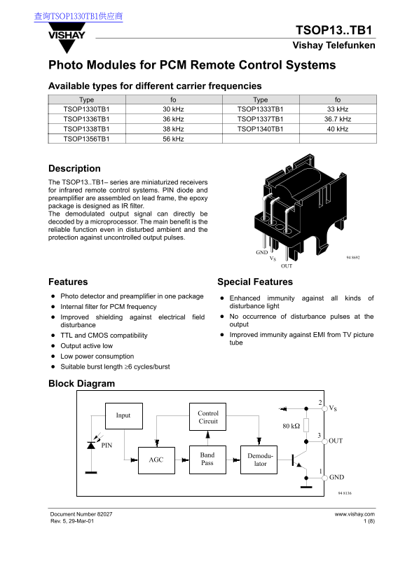
Page 1 Text Content
查询TSOP1330TB1供应商
TSOP13..TB1 Vishay Telefunken
Photo Modules for PCM Remote Control Systems Available types for different carrier frequencies Type fo Type fo TSOP1330TB1 30 k Hz TSOP1333TB1 33 k Hz TSOP1336TB1 36 k Hz TSOP1337TB1 36.7 k Hz TSOP1338TB1 38 k Hz TSOP1340TB1 40 k Hz TSOP1356TB1 56 k Hz
Description The TSOP13..TB1– series are miniaturized receivers for infrared remote control systems. PIN diode and preamplifier are assembled on lead frame, the epoxy package is designed as IR filter. The demodulated output signal can directly be decoded by a microprocessor. The main benefit is the reliable function even in disturbed ambient and the protection against uncontrolled output pulses.
VS 94 8692
Features Special Features Photo detector and preamplifier in one package
Enhanced immunity against all kinds of Internal filter for PCM frequency disturbance light Improved shielding against electrical field No occurrence of disturbance pulses at the disturbance output TTL and CMOS compatibility Improved immunity against EMI from TV picture tube
Output active low Low power consumption Suitable burst length ≥6 cycles/burst
Block Diagram
Control
Input
Circuit
Band Demodu-
Pass lator
www.vishay.com Document Number 82027
1 (8)Rev. 5, 29-Mar-01
Page Summary Contents For Vishay TSOP13..TB1 Data Sheet
Manual Details
| Brand | Vishay |
|---|---|
| Pages | 9 |
| File Size | 236.40 KB |
| Published | June 01, 2026 |
Enter the captcha to get the download link:

Frequently Asked Questions
What environmental conditions affect this module's operation?
The operating temperature range is -25°C to +85°C, and it has a maximum junction temperature of 100°C.
How does the TSOP13..TB1 resist background interference?
It provides enhanced immunity by including an internal filter for PCM frequency and robust shielding against electrical field output disturbance.
What are the typical required parameters for reliable data signals?
The carrier frequency should be close to the center, the burst length must be 6 cycles/burst or longer, and a gap time of at least 12 cycles is necessary after each burst.