Vishay SFH610A SFH6106 Specifications and User Guide
Summary
Secure signal transfer between electrically isolated circuits using these high-reliability optocouplers (SFH610A/SFH6106). This product line features dedicated models with precise CTR ratios, robust isolation voltages up to 5300 V RMS, and enhanced performance factors like low capacitance and fast switching times. Perfect for electronics designers and engineers needing dependable signal coupling in demanding industrial and commercial applications. The manual provides comprehensive specifications for both DIP and SMD packages.
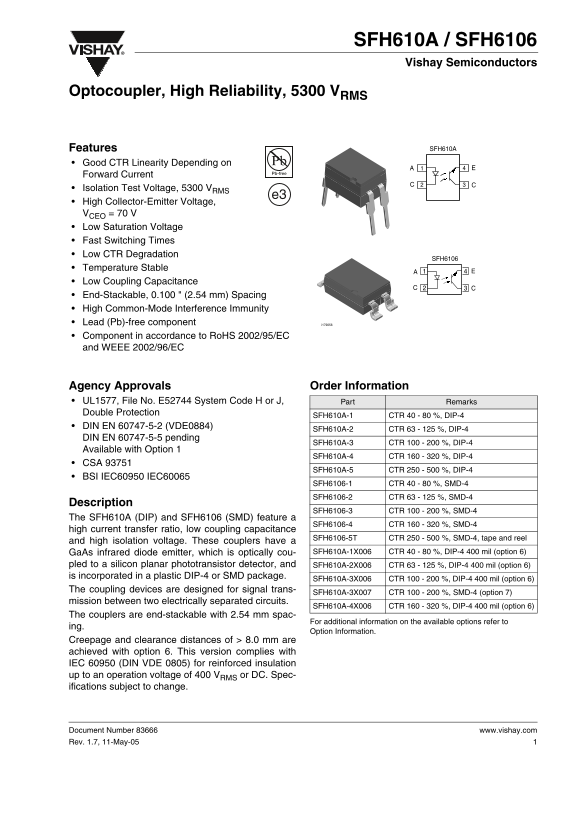
Page 1 Text Content
SFH610A / SFH6106 Vishay Semiconductors
Optocoupler, High Reliability, 5300 VRMS
Features SFH610A
Good CTR Linearity Depending on Forward Current Isolation Test Voltage, 5300 VRMS
High Collector-Emitter Voltage, VCEO = 70 V Low Saturation Voltage Fast Switching Times Low CTR Degradation
SFH6106
Temperature Stable Low Coupling Capacitance End-Stackable, 0.100 " (2.54 mm) Spacing High Common-Mode Interference Immunity Lead (Pb)-free component i179056 Component in accordance to Ro HS 2002/95/EC and WEEE 2002/96/EC
Agency Approvals Order Information UL1577, File No. E52744 System Code H or J, Part Remarks Double Protection
SFH610A-1 CTR 40 - 80 %, DIP-4
DIN EN 60747-5-2 (VDE0884)
SFH610A-2 CTR 63 - 125 %, DIP-4
DIN EN 60747-5-5 pending
SFH610A-3 CTR 100 - 200 %, DIP-4
Available with Option 1
SFH610A-4 CTR 160 - 320 %, DIP-4
CSA 93751
SFH610A-5 CTR 250 - 500 %, DIP-4
BSI IEC60950 IEC60065
SFH6106-1 CTR 40 - 80 %, SMD-4 SFH6106-2 CTR 63 - 125 %, SMD-4
Description
SFH6106-3 CTR 100 - 200 %, SMD-4
The SFH610A (DIP) and SFH6106 (SMD) feature a
SFH6106-4 CTR 160 - 320 %, SMD-4
high current transfer ratio, low coupling capacitance
SFH6106-5T CTR 250 - 500 %, SMD-4, tape and reel
and high isolation voltage. These couplers have a
Ga As infrared diode emitter, which is optically cou- SFH610A-1X006 CTR 40 - 80 %, DIP-4 400 mil (option 6)
pled to a silicon planar phototransistor detector, and SFH610A-2X006 CTR 63 - 125 %, DIP-4 400 mil (option 6) is incorporated in a plastic DIP-4 or SMD package.
SFH610A-3X006 CTR 100 - 200 %, DIP-4 400 mil (option 6)
The coupling devices are designed for signal trans-
SFH610A-3X007 CTR 100 - 200 %, SMD-4 (option 7)
mission between two electrically separated circuits.
SFH610A-4X006 CTR 160 - 320 %, DIP-4 400 mil (option 6)
The couplers are end-stackable with 2.54 mm spac-
For additional information on the available options refer to
Option Information.
Creepage and clearance distances of > 8.0 mm are achieved with option 6. This version complies with IEC 60950 (DIN VDE 0805) for reinforced insulation up to an operation voltage of 400 VRMS or DC. Spec- ifications subject to change.
Document Number 83666 www.vishay.com Rev. 1.7, 11-May-05
Page Summary Contents For Vishay SFH610A SFH6106 Specifications and User Guide
Manual Details
| Brand | Vishay |
|---|---|
| Pages | 10 |
| File Size | 752.20 KB |
| Published | May 31, 2026 |
Enter the captcha to get the download link:

Frequently Asked Questions
What is the primary function of the SFH610A/SFH6106 couplers?
They are designed for signal transmission between two electrically separated circuits.
What high isolation voltage can these units support?
The devices offer an isolation test voltage up to 5300 V RMS.
How does the packaging facilitate multiple units?
The couplers are end-stackable with a spacing of 2.54 mm.
Are these components environmentally compliant?
Yes, they are lead (Pb)-free and comply with RoHS guidelines.