Vishay RCWP Data Sheet User Guide
Summary
These high-reliability thick film chip resistors offer robust performance across extreme temperatures (-55°C to +150°C), meeting demanding industrial standards like MIL-PRF-55342. Ideal for electronics manufacturers, these components feature highly configurable options, including size, resistance value, and both tin/lead and lead-free terminations. The manual provides comprehensive global part numbering, detailed electrical specifications, dimensions, and reliability data, enabling engineers to source the perfect precise resistor solution for specialized circuit designs.
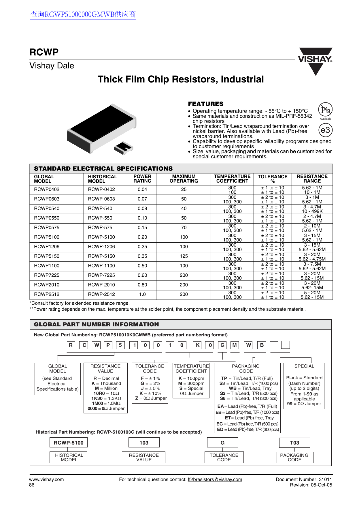
Page 1 Text Content
查询RCWP51000000GMWB供应商
RCWP Vishay Dale
Thick Film Chip Resistors, Industrial
FEATURES Operating temperature range: - 55°C to + 150°C Same materials and construction as MIL-PRF-55342
Available
chip resistors Termination: Tin/Lead wraparound termination over
nickel barrier. Also available with Lead (Pb)-free e3
wraparound terminations. Capability to develop specific reliability programs designed to customer requirements Size, value, packaging and materials can be customized for special customer requirements.
STANDARD ELECTRICAL SPECIFICATIONS
GLOBAL HISTORICAL POWER MAXIMUM TEMPERATURE TOLERANCE RESISTANCE MODEL MODEL RATING OPERATING COEFFICIENT RANGE
± 1 to ± 10 5.62 - 1M
RCWP0402 RCWP-0402 0.04
± 1 to ± 10 10 - 1M ± 2 to ± 10 3 - 1M
RCWP0603 RCWP-0603 0.07
100, 300 ± 1 to ± 10 5.62 - 1M
± 2 to ± 10 3 - 4.7M
RCWP0540 RCWP-540 0.08
100, 300 ± 1 to ± 10 10 - 499K
± 2 to ± 10 2 - 4.7M
RCWP0550 RCWP-550 0.10
100, 300 ± 1 to ± 10 5.62 - 1M
± 2 to ± 10 2 - 10M
RCWP0575 RCWP-575 0.15
100, 300 ± 1 to ± 10 5.62 - 1M
± 2 to ± 10 3 - 15M
RCWP5100 RCWP-5100 0.20
100, 300 ± 1 to ± 10 5.62 - 1M
± 2 to ± 10 3 - 15M
RCWP1206 RCWP-1206 0.25
100, 300 ± 1 to ± 10 5.62 - 5.62M
± 2 to ± 10 3 - 20M
RCWP5150 RCWP-5150 0.35
100, 300 ± 1 to ± 10 5.62 - 4.75M
± 2 to ± 10 3 - 7.5M
RCWP1100 RCWP-1100 0.50
100, 300 ± 1 to ± 10 5.62 - 5.62M
± 2 to ± 10 3 - 20M
RCWP7225 RCWP-7225 0.60
100, 300 ± 1 to ± 10 5.62 - 15M
± 2 to ± 10 3 - 20M
RCWP2010 RCWP-2010 0.80
100, 300 ± 1 to ± 10 5.62- 15M
± 2 to ± 10 5 - 20M
RCWP2512 RCWP-2512 1.0
100, 300 ± 1 to ± 10 5.62 - 15M
*Consult factory for extended resistance range. **Power rating depends on the max. temperature at the solder point, the component placement density and the substrate material.
GLOBAL PART NUMBER INFORMATION New Global Part Numbering: RCWP510010K0GMWB (preferred part numbering format)
GLOBAL RESISTANCE TOLERANCE TEMPERATURE PACKAGING SPECIAL MODEL VALUE CODE COEFFICIENT CODE
R = Decimal F = ± 1% K = 100ppm TP = Tin/Lead, T/R (Full) Blank = Standard(see Standard
Electrical K = Thousand G = ± 2% M = 300ppm S3 = Tin/Lead, T/R (1000 pcs) (Dash Number) Specifications table) M = Million J = ± 5% S = Special, WB = Tin/Lead, Tray (up to 2 digits) 10R0 = 10Ω K = ± 10% 0Ω Jumper S2 = Tin/Lead, T/R (500 pcs) From 1-99 as
1K30 = 1.3KΩ Z = 0Ω Jumper S6 = Tin/Lead, T/R (300 pcs) applicable
1M00 = 1.0MΩ 99 = 0Ω Jumper
EA= Lead (Pb)-free, T/R (Full)
0000 = 0Ω Jumper
EB= Lead (Pb)-free, T/R (1000 pcs)
ET = Lead (Pb)-free, Tray EC = Lead (Pb)-free, T/R (500 pcs) ED = T/R (300 pcs) Lead (Pb)-free,
Historical Part Numbering: RCWP-5100103G (will continue to be accepted)
RCWP-5100 T03
HISTORICAL RESISTANCE TOLERANCE PACKAGING MODEL VALUE CODE CODE
www.vishay.com For technical questions contact: [email protected] Document Number: 31011 Revision: 05-Oct-05
Page Summary Contents For Vishay RCWP Data Sheet User Guide
Manual Details
| Brand | Vishay |
|---|---|
| Pages | 3 |
| File Size | 212.42 KB |
| Published | July 16, 2026 |
Enter the captcha to get the download link:
