Vishay MBR15HxxCT, MBRF15HxxCT, MBRB15HxxCT Series Data Manual
Summary
These dual Schottky Barrier Rectifiers offer reliable, high-efficiency power conversion for demanding DC applications, ranging from 35V to 60V blocking voltages and 15A current handling. This comprehensive guide details product specifications, including electrical characteristics, thermal management data, maximum safety ratings (e.g., reverse surge), and mounting instructions for various packages. It is essential reading for power electronics engineers and hardware designers building low-voltage inverters or industrial DC systems requiring robust performance.
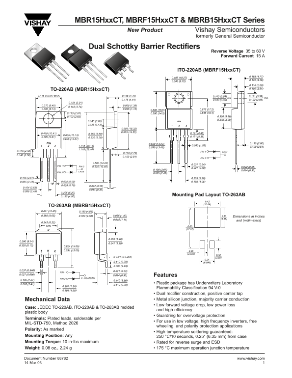
Page 1 Text Content
MBR15Hxx CT, MBRF15Hxx CT & MBRB15Hxx CT Series
New Product Vishay Semiconductors
formerly General Semiconductor
Dual Schottky Barrier Rectifiers
Reverse Voltage 35 to 60 V Forward Current 15 A
ITO-220AB (MBRF15Hxx CT)
TO-220AB (MBR15Hxx CT)
0.415 (10.54) MAX. 0.185 (4.70) 0.140 (3.56) 0.131 (3.39)
DIA.DIA.
0.145 (3.68) PIN 0.135 (3.43)
PIN 0.560 (14.22) 0.110 (2.80)
0.160 (4.06) PIN 2PIN 1
PIN 3
PIN 1 PIN 2 0.530 (13.46)
PIN 3 CASE
Mounting Pad Layout TO-263AB
TO-263AB (MBRB15Hxx CT) 0.411 (10.45) 0.190 (4.83) 0.380 (9.65) 0.160 (4.06) 0.055 (1.40) 0.33 Dimensions in inches
and (millimeters)
0.245 (6.22) MIN 0.63
PIN 1
0.027 (0.686) 0.014 (0.36) Features
PIN 2 K - HEATSINK
0.095 (2.41) • Plastic package has Underwriters Laboratory
Flammability Classification 94 V-0
• Dual rectifier construction, positive center tap Mechanical Data • Metal silicon junction, majority carrier conduction • Low forward voltage drop, low power loss
Case: JEDEC TO-220AB, ITO-220AB & TO-263AB molded
and high efficiency
plastic body
• Guardring for overvoltage protection
Terminals: Plated leads, solderable per
• For use in low voltage, high frequency inverters, free
MIL-STD-750, Method 2026
wheeling, and polarity protection applications
Polarity: As marked
• High temperature soldering guaranteed:
Mounting Position: Any 250 °C/10 seconds, 0.25" (6.35 mm) from case Mounting Torque: 10 in-lbs maximum • Rated for reverse surge and ESD
Weight: 0.08 oz., 2.24 g • 175 °C maximum operation junction temperature
Document Number 88782 www.vishay.com 14-Mar-03
Page Summary Contents For Vishay MBR15HxxCT, MBRF15HxxCT, MBRB15HxxCT Series Data Manual
Manual Details
| Brand | Vishay |
|---|---|
| Pages | 4 |
| File Size | 94.75 KB |
| Published | May 31, 2026 |
Enter the captcha to get the download link:

Frequently Asked Questions
What is the maximum operating junction temperature?
The maximum operational junction temperature range is -65 to +175 °C.
Can these rectifiers withstand ESD?
Yes, they are rated for an Electrostatic discharge (ESD) voltage of 25 kV.
What torque should be used when mounting the device?
The recommended mounting torque is a maximum of 10 in-lbs.
Which specific model handles a reverse surge of 60V?
The MBR15H60CT, MBRF15H60CT, and MBRB15H60CT series are rated for a Reverse Voltage of 60 V.