Vishay IHLP-5050CE-01 Data Sheet User Manual
Summary
This precision low profile inductor series is designed for sophisticated power management applications requiring high current handling and minimal size. Featuring shielded construction and ultra-low DC resistance, it maintains stability across various frequency ranges and handles transient spikes common in modern electronic systems. The accompanying manual provides comprehensive electrical specifications, detailed performance graphs, and thermal guidelines, making it an essential resource for circuit designers building portable devices, industrial servers, high-current POL converters, and robust DC/DC power solutions (including those using FPGAs).
Page 1 Text Content
查询IHLP-5050CE-01供应商
IHLP-5050CE-01 Vishay Dale
Low Profile, High Current Inductor
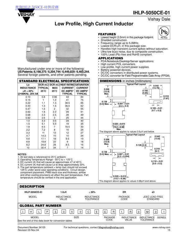
FEATURES Lowest height (3.5mm) in this package footprint. Shielded construction. Frequency range up to 5.0MHz. Lowest DCR/µH, in this package size. Handles high transient current spikes without saturation. Ultra low buzz noise, due to composite construction. 100% Lead (Pb)-free and Ro HS compliant. APPLICATIONS PDA/Notebook/Desktop/Server applications. High current POL converters. Low profile, high current power supplies.
Manufactured under one or more of the following:
Battery powered devices.
US Patents; 6,198,375 / 6,204,744 / 6,449,829 / 6,460,244.
DC/DC converters in distributed power systems.
Several foreign patents, and other patents pending.
DC/DC converter for Field Programmable Gate Array (FPGA).
STANDARD ELECTRICAL SPECIFICATIONS DIMENSIONS in inches [millimeters]
Typical Pad Layout
Lo DCR mΩ DCR mΩ HEAT RATING SATURATION
0.542 INDUCTANCE TYPICAL MAX CURRENT CURRENT [13.76]
µH ± 20% 25°C 25°C DC AMPS3 DC AMPS4 0.195
@100KHz, .25V, 0A TYPICAL TYPICAL Max.
[3.5] Max. 0.091 ± 0.01 0.33 1.3 1.5 36.5 [2.3 ± 0.3]
The diagram above applies to values 0.6µH and below.
Typical Pad Layout
0.508 6.8 19.8 [12.9] Max.
NOTES: [3.5] Max. 0.087 ± 0.01 [2.2 ± 0.254]
1. All test data is referenced to 25°C ambient. 2. Operating Temperature Range - 55°C to + 125°C
3. DC current (A) that will cause an approximate ∆T of 40°C.
4. DC current (A) that will cause Lo to drop approximately 20% 5. The part temperature (ambient + temp rise) should not exceed 125°C under worst case operating conditions. Circuit design, component placement, PWB trace size and thickness, airflow and other cooling provisions all affect the part temperature. Part
temperature should be verified in the end application.
The diagram above applies to values 0.68µH and above.
DESCRIPTION IHLP-5050CE-01 1.0µH ± 20% ER e3
MODEL INDUCTANCE INDUCTANCE PACKAGE JDEC LEAD FREE
VALUE TOLERANCE CODE STANDARD
GLOBAL PART NUMBER
MODEL SIZE PACKAGE INDUCTANCE INDUCTANCE SERIES
CODE VALUE TOLERANCE
See the end of this data book for conversion tables
Document Number 34105 For technical questions, contact [email protected] www.vishay.com Revision 03-Nov-04
Page Summary Contents For Vishay IHLP-5050CE-01 Data Sheet User Manual
Manual Details
| Brand | Vishay |
|---|---|
| Pages | 4 |
| File Size | 149.84 KB |
| Published | June 01, 2026 |
Enter the captcha to get the download link:
