Vishay CS201 Data Sheet
Summary
Engineers utilize these Single-In-Line Capacitor Networks (SIP) for high-reliability electronics design. Featuring a D profile and multiple isolated capacitor grids (X7R/COG), this component is ideal for demanding circular circuits operating from -55°C to +125°C, while remaining RoHS compliant. The manual provides comprehensive technical specifications, detailing electrical tolerances, mechanical dimensions, customizable global part numbering, and MIL-STD testing parameters to ensure precise integration into durable printed circuit boards.
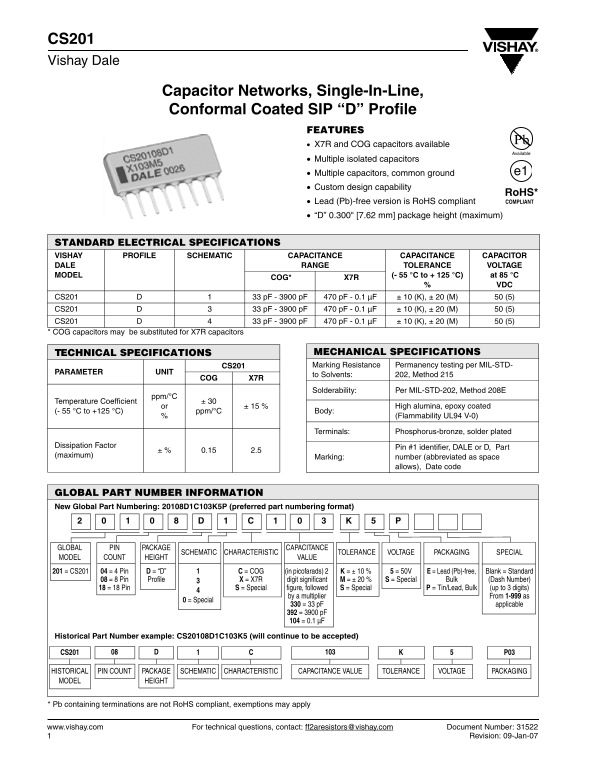
Page 1 Text Content
CS201 Vishay Dale
Capacitor Networks, Single-In-Line, Conformal Coated SIP “D” Profile
FEATURES X7R and COG capacitors available
Available
Multiple isolated capacitors
Multiple capacitors, common ground e1
Custom design capability
Ro HS* Lead (Pb)-free version is Ro HS compliant COMPLIANT
“D” 0.300" [7.62 mm] package height (maximum)
STANDARD ELECTRICAL SPECIFICATIONS
VISHAY PROFILE SCHEMATIC CAPACITANCE CAPACITANCE CAPACITOR DALE RANGE TOLERANCE VOLTAGE MODEL (- 55 °C to + 125 °C) at 85 °C
COG* X7R
CS201 33 p F - 3900 p F 470 p F - 0.1 µF ± 10 (K), ± 20 (M) 50 (5) CS201 33 p F - 3900 p F 470 p F - 0.1 µF ± 10 (K), ± 20 (M) 50 (5) CS201 33 p F - 3900 p F 470 p F - 0.1 µF ± 10 (K), ± 20 (M) 50 (5) * COG capacitors may be substituted for X7R capacitors
TECHNICAL SPECIFICATIONS MECHANICAL SPECIFICATIONS CS201 Marking Resistance Permanency testing per MIL-STD-
PARAMETER UNIT
to Solvents: 202, Method 215
COG X7R
Solderability: Per MIL-STD-202, Method 208E
ppm/°C
Temperature Coefficient ± 30
or ± 15 % High alumina, epoxy coated
(- 55 °C to +125 °C) ppm/°C Body:
(Flammability UL94 V-0)
Terminals: Phosphorus-bronze, solder plated
Dissipation Factor Pin #1 identifier, DALE or D, Part
(maximum) Marking: number (abbreviated as space
allows), Date code
GLOBAL PART NUMBER INFORMATION New Global Part Numbering: 20108D1C103K5P (preferred part numbering format)
GLOBAL PIN PACKAGE CAPACITANCE
SCHEMATIC CHARACTERISTIC TOLERANCE VOLTAGE PACKAGING SPECIAL
MODEL COUNT HEIGHT VALUE
201 = CS201 04 = 4 Pin D = “D” C = COG (in picofarads) 2 K = ± 10 % 5 = 50V E = Lead (Pb)-free, Blank = Standard
08 = 8 Pin Profile X = X7R digit significant M = ± 20 % S = Special Bulk (Dash Number) 18 = 18 Pin S = Special figure, followed S = Special P = Tin/Lead, Bulk (up to 3 digits)
by a multiplier From 1-999 as
0 = Special
330 = 33 p F applicable 392 = 3900 p F 104 = 0.1 µF
Historical Part Number example: CS20108D1C103K5 (will continue to be accepted)
CS201 P03
HISTORICAL PIN COUNT PACKAGE SCHEMATIC CHARACTERISTIC CAPACITANCE VALUE TOLERANCE VOLTAGE PACKAGING MODEL HEIGHT
* Pb containing terminations are not Ro HS compliant, exemptions may apply
www.vishay.com For technical questions, contact: [email protected] Document Number: 31522 Revision: 09-Jan-07
Page Summary Contents For Vishay CS201 Data Sheet
Manual Details
| Brand | Vishay |
|---|---|
| Pages | 3 |
| File Size | 111.71 KB |
| Published | June 06, 2026 |
Enter the captcha to get the download link:
