VISHAY BFP93A BFP93AW Data Sheet
Summary
These high-performance NPN Planar RF Transistors are ideal for designers requiring robust amplification in the GHz range. Featuring low noise figure and high power gain in SOT-143 and SOT-343 packages, these components meet demanding signal integrity needs. The technical manual provides comprehensive electrical parameters, s-parameters, and detailed usage guidelines necessary for integrating the RF transistors into professional electronic circuits.
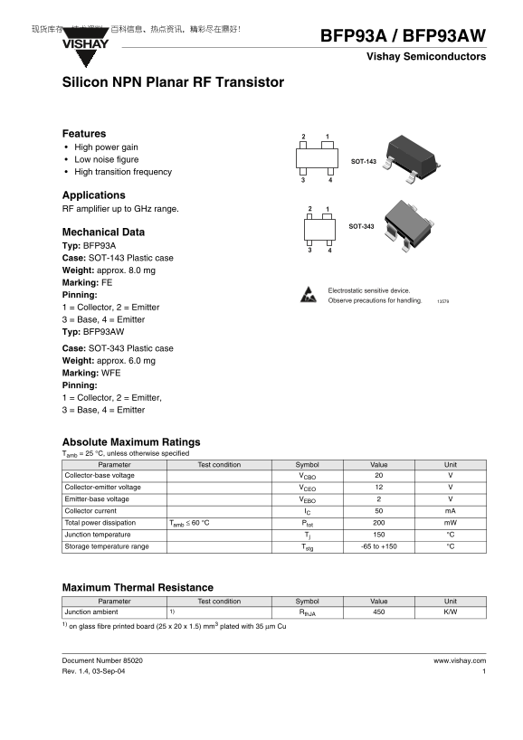
Page 1 Text Content
BFP93A / BFP93AW
VISHAY
Vishay Semiconductors
Silicon NPN Planar RF Transistor
Features High power gain Low noise figure SOT-143 High transition frequency
Applications RF amplifier up to GHz range.
SOT-343
Mechanical Data Typ: BFP93A Case: SOT-143 Plastic case Weight: approx. 8.0 mg Marking: FE
Electrostatic sensitive device.
Pinning:
Observe precautions for handling.
1 = Collector, 2 = Emitter 3 = Base, 4 = Emitter Typ: BFP93AW
Case: SOT-343 Plastic case Weight: approx. 6.0 mg Marking: WFE Pinning: 1 = Collector, 2 = Emitter, 3 = Base, 4 = Emitter
Absolute Maximum Ratings Tamb = 25 °C, unless otherwise specified
Parameter Test condition Symbol Value Unit
Collector-base voltage VCBO Collector-emitter voltage VCEO Emitter-base voltage VEBO
Collector current IC m A
Total power dissipation Tamb ≤ 60 °C Ptot m W
Junction temperature Tj °C
Storage temperature range Tstg -65 to +150 °C
Maximum Thermal Resistance Parameter Test condition Symbol Value Unit
Junction ambient 1) Rth JA K/W
1) on glass fibre printed board (25 x 20 x 1.5) mm3 plated with 35 µm Cu
Document Number 85020 www.vishay.com Rev. 1.4, 03-Sep-04
Page Summary Contents For VISHAY BFP93A BFP93AW Data Sheet
Manual Details
| Brand | Vishay |
|---|---|
| Pages | 9 |
| File Size | 220.12 KB |
| Published | May 28, 2026 |
Enter the captcha to get the download link:

Frequently Asked Questions
What types of packages/cases are available for this transistor?
The transistors are available in two cases: SOT-143 (for BFP93A) and SOT-343 (for BFP93AW).
Is there a limit on the total power dissipation (P_tot)?
Yes, the maximum total power dissipation must not exceed 200 mW when ambient temperature is at or below 60 °C.
Are there special handling requirements for this component?
It is an electrostatic sensitive device, and physical precautions should be observed during handling.