Vishay 307C Data Sheet
Summary
These PTC thermistors are essential components for electronic fluorescent ballasts and CFLs, designed to provide reliable electrode preheating current limiting and flicker-free operation while extending overall lamp life. This technical manual provides comprehensive data, including specifications on instantaneous/continuous voltages, required preheat currents, and part selection guidance for optimizing ignition time. It is specifically intended for lighting designers and engineers who require high-performance, economical components for advanced fluorescent fixture systems.
Page 1 Text Content
查询307C1171供应商 307C Lighting Thermistors Vishay Cera-Mite PTC Thermistors For Electronic Fluorescent Ballasts
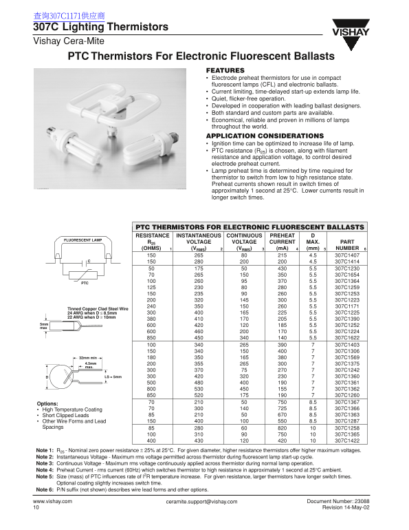
FEATURES Electrode preheat thermistors for use in compact fluorescent lamps (CFL) and electronic ballasts. Current limiting, time-delayed start-up extends lamp life. Quiet, flicker-free operation. Developed in cooperation with leading ballast designers. Both standard and custom parts are available. Economical, reliable and proven in millions of lamps throughout the world. APPLICATION CONSIDERATIONS Ignition time can be optimized to increase life of lamp. PTC resistance (R25) is chosen, along with filament resistance and application voltage, to control desired electrode preheat current. Lamp preheat time is determined by time required for thermistor to switch from low to high resistance state. Preheat currents shown result in switch times of approximately 1 second at 25°C. Lower currents result in longer switch times.
PTC THERMISTORS FOR ELECTRONIC FLUORESCENT BALLASTS RESISTANCE INSTANTANEOUS CONTINUOUS PREHEAT
FLUORESCENT LAMP
R25 VOLTAGE VOLTAGE CURRENT MAX. PART (OHMS) (VRMS) (VRMS) (m A) (mm) NUMBER
Tinned Copper Clad Steel Wire
24 AWG when D ≤ 8.5mm 5.5 307C1225
22 AWG when D ≥ 10mm
32mm min 307C1569 4.5mm 307C1375 max.
307C1242 LS = 5mm D 307C1360 307C1361 307C1362 307C1260
Options:
High Temperature Coating 8.5 307C1366 Short Clipped Leads 8.5 307C1363 Other Wire Forms and Lead 8.5 307C1287
Spacings 307C1258
Note 1: R25 - Nominal zero power resistance ± 25% at 25°C. For given diameter, higher resistance thermistors offer higher maximum voltages. Note 2: Instantaneous Voltage - Maximum rms voltage permitted across thermistor during fluorescent lamp start-up cycle. Note 3: Continuous Voltage - Maximum rms voltage continuously applied across thermistor during normal lamp operation. Note 4: Preheat Current - rms current (60Hz) which switches thermistor to high resistance in approximately 1 second at 25°C ambient. Note 5: Size (mass) of PTC influences rate of I2R temperature increase. For given resistance, larger thermistors have longer switch times.
Optional coating slightly increases switch time.
Note 6: P/N suffix (not shown) describes wire lead forms and other options.
www.vishay.com [email protected] Document Number: 23088
Revision 14-May-02
Page Summary Contents For Vishay 307C Data Sheet
Manual Details
| Brand | Vishay |
|---|---|
| Pages | 1 |
| File Size | 254.67 KB |
| Published | June 15, 2026 |
Enter the captcha to get the download link:

Frequently Asked Questions
What is the purpose of these PTC thermistors?
They are electrode preheat thermistors specifically designed for use in compact fluorescent lamps (CFL) and electronic ballasts.
How does the resistance affect performance?
For a given diameter, higher resistance thermistors allow for higher maximum voltages. Also, larger thermistors tend to have longer switch times for a given resistance.
What determines the optimal ignition time?
The ignition time can be optimized by selecting an appropriate PTC resistance (R), along with filament and application voltage, to control the desired electrode preheat current.
How long does preheating take?
Preheat currents result in switch times of approximately 1 second at 25°C. Lower applied currents will lead to longer switch times.