Toshiba TOTX140 Data Handbook
Summary
This fiber optic transmitting module is engineered for reliable digital audio interconnects, conforming to JEITA standards for various professional and consumer audio applications. This technical guide provides comprehensive specifications, covering electrical parameters, optical data rates up to 6 Mb/s, mechanical mounting details, and application circuit diagrams. It serves as a vital resource for electronics engineers designing general audio equipment—including industrial, office, or personal devices—who require high-quality fiber optic signal transmission integration knowledge and best practices.
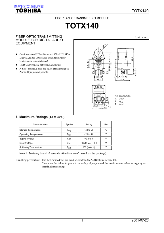
Page 1 Text Content
查询TOTX140供应商
TOTX140
FIBER OPTIC TRANSMITTING MODULE
TOTX140
FIBER OPTIC TRANSMITTING Unit: mm MODULE FOR DIGITAL AUDIO EQUIPMENT
Conforms to JEITA Standard CP−1201 (For Digital Audio Interfaces including Fiber Optic inter−connections). LED is driven by differential circuit. A Self−tapping hole for easy attachment to Audio Equipment panels.
1. Maximum Ratings (Ta = 25°C)
Characteristics Symbol Rating Unit
Storage Temperature Tstg −40 to 70 °C Operating Temperature Topr −20 to 70 °C Supply Voltage VCC −0.5 to 7 V Input Voltage VIN −0.5 to VCC + 0.5 V Soldering Temperature Tsol 260 (Note 1) °C
Note 1: Soldering time ≤ 10 seconds (At a distance of 1 mm from the package).
Handling precaution: The LED’s used in this product contain Ga As (Gallium Arsenide).
Care must be taken to protect the safety of people and the environment when scrapping or terminal processing.
Page Summary Contents For Toshiba TOTX140 Data Handbook
Manual Details
| Brand | Toshiba |
|---|---|
| Pages | 7 |
| File Size | 114.21 KB |
| Published | June 02, 2026 |
Enter the captcha to get the download link:

Frequently Asked Questions
What precautions must be taken when handling or disposing of this module?
The LED contains GaAs (Gallium Arsenide); do not break, cut, pulverize, or dissolve it with chemicals during disposal. Follow appropriate regulations.
Over what voltage range should I operate the component?
The recommended supply voltage range is 2.7 V to 3.6 V CC.
How should I monitor the longevity of the light emitter?
Monitor the fiber output power ($P_f$) periodically, as its lifetime is highly influenced by operating conditions and usage environment.
Are there specific rules for soldering or installation?
Soldering is not recommended; if necessary, use non-halogen (chlorine-free) flux and ensure no residue remains after cleaning.