Toshiba TLP705 User's Manual
Summary
This high-performance photocoupler is a robust optoisolator utilizing GaAℓAs technology for safe, reliable power switching. Designed with reinforced insulation standards, it excels as a gate driver solution for IGBTs and power MOS FETs, even supporting direct low-power IGBT drives. This comprehensive manual provides detailed technical specifications, including maximum ratings, electrical characteristics (isolation voltage up to 5000 Vrms), timing diagrams, and recommended application circuits. Ideal for engineers developing industrial inverters, plasma displays, or any power electronic system requiring high safety isolation and reliable operation across wide temperature ranges.
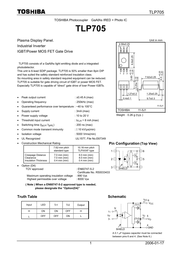
Page 1 Text Content
TLP705
TOSHIBA Photocoupler Ga AℓAs IRED + Photo IC
TLP705
Plasma Display Panel. Unit in mm
Industrial Inverter
IGBT/Power MOS FET Gate Drive
TLP705 consists of a Ga AℓAs light emitting diode and a integrated photodetector. This unit is 6-lead SDIP package. TLP705 is 50% smaller than 8pin DIP
and has suited the safety standard reinforced insulation class.
So mounting area in safety standard required equipment can be reduced. TLP705 is suitable for gate driving circuit of IGBT or power MOS FET. Especially TLP705 is capable of “direct” gate drive of lowr Power IGBTs.
• Peak output current : ±0.45 A (max)
• Operating frequency : 250k Hz (max)
• Guaranteed performance over temperature : −40 to 100°C
TOSHIBA 11-5J1
• Supply current : 3m A (max)
Weight:0.26 g (typ.)
• Power supply voltage : 10 to 20 V • Threshold input current : IFLH = 8 m A (max) • Switching time (tp LH / tp HL) : 200 ns (max) • Common mode transient immunity :±10 k V/µs(min)
• Isolation voltage : 5000 Vrms(min)
• UL Recognized :UL1577, File No.E67349 • Construction Mechanical Rating Pin Configuration (Top View)
7.62-mm pitch 10.16-mm pitch standard type TLPXXXF type
Creepage Distance 7.0 mm (min) 8.0 mm (min) Clearance 7.0 mm (min) 8.0 mm (min)
Insulation Thickness 0.4 mm (min) 0.4 mm (min) +0 .2 4. −0 .2
• Option (D4)
TÜV approved : EN60747-5-2 SHIELD
Certificate No. R50033433 Maximum operating insulation voltage : 890 Vpk Highest permissible over voltage : 8000 Vpk ( Note ) When a EN60747-5-2 approved type is needed, please designate the “Option(D4)”
Truth Table Schematic
ICC VCC
Input LED Tr1 Tr2 Output (Tr1)
H ON ON OFF H
VF IO
L OFF OFF ON L
3− (Tr2) VO
SHIELD A 0.1 µF bypass capacitor must be connected between pins 6 and 4. (See Note 6.)
Page Summary Contents For Toshiba TLP705 User's Manual
Manual Details
| Brand | Toshiba |
|---|---|
| Pages | 6 |
| File Size | 224.14 KB |
| Published | June 06, 2026 |
Enter the captcha to get the download link:
