TOSHIBA TC7SH86FE User's Manual
Summary
This high-speed CMOS Digital Integrated Circuit is a reliable Exclusive OR (XOR) Gate designed for general electronics applications. The accompanying datasheet provides comprehensive technical specifications, including operating voltage ranges (2–5.5V), low power dissipation metrics, and detailed electrical characteristics necessary for design validation. It covers DC/AC parameters, propagation delays, and operational guidelines. Essential reading for electronics engineers and circuit designers developing stable digital systems used in computing, industrial robotics, or office equipment requiring precise logic functionality.
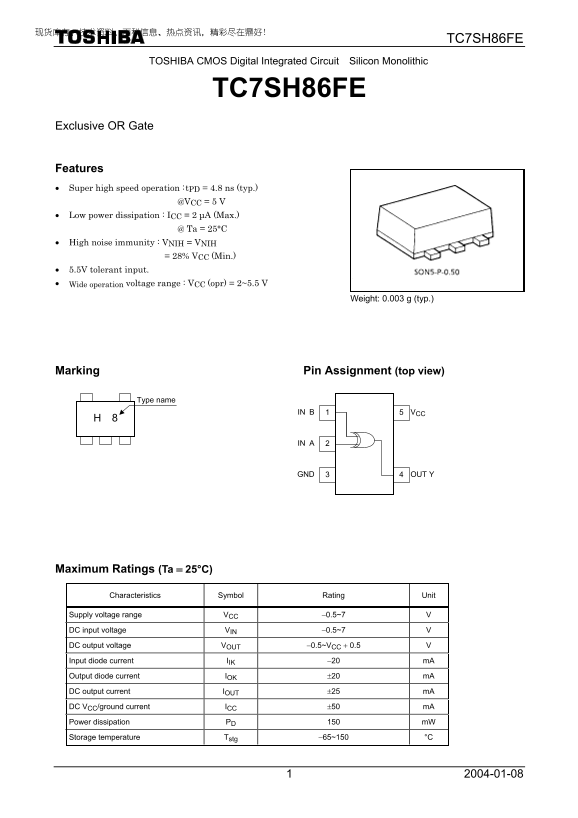
Page 1 Text Content
TC7SH86FE
TOSHIBA CMOS Digital Integrated Circuit Silicon Monolithic
TC7SH86FE
Exclusive OR Gate
Features • Super high speed operation : t PD = 4.8 ns (typ.) @VCC = 5 V • Low power dissipation : ICC = 2 µA (Max.) @ Ta = 25°C • High noise immunity : VNIH = VNIH = 28% VCC (Min.) • 5.5V tolerant input. • Wide operation voltage range : VCC (opr) = 2~5.5 V
Weight: 0.003 g (typ.)
Marking Pin Assignment (top view)
Type name
H 8 IN B
OUT Y
Maximum Ratings (Ta = 25°C)
Characteristics Symbol Rating Unit
Supply voltage range VCC −0.5~7 V
DC input voltage VIN −0.5~7 V
DC output voltage VOUT −0.5~VCC + 0.5 V
Input diode current IIK −20 m A
Output diode current IOK ±20 m A
DC output current IOUT ±25 m A
DC VCC/ground current ICC ±50 m A
Power dissipation PD 150 m W
Storage temperature Tstg −65~150 °C
Page Summary Contents For TOSHIBA TC7SH86FE User's Manual
Manual Details
| Brand | Toshiba |
|---|---|
| Pages | 5 |
| File Size | 119.87 KB |
| Published | May 31, 2026 |
Enter the captcha to get the download link:

Frequently Asked Questions
What is the typical operation speed of this chip?
The characteristic propagation delay time (t) is typically 4.8 ns.
What is the recommended voltage operating range for use?
The specified supply voltage V is 2 to 5.5 V, and input voltage is 0 to 5.5 V.
How much power does the chip dissipate during operation?
The typical power dissipation (PD) at V = 5V is listed as 150 mW.
Are there any usage restrictions I should know about?
It is intended for general electronics applications but should not be used in equipment requiring extraordinarily high quality or reliability, like medical instruments or life-support systems.