Toshiba Photocoupler GaAℓAs IRed & Photo−IC TLP651 Specifications (1)(1) Owner's Manual & User Guide
Summary
The TLP651 is a high-isolation photocoupler signal unit featuring a GaAlAs LED and photo-transistor. It provides superior electrical separation (up to 5000V) for critical signals, making it essential for microprocessor interfacing, line receiving, and general logic isolation in demanding applications. This comprehensive manual details its performance characteristics, including switching times, absolute ratings, and common mode immunity specifications. It is designed for reliability-critical industrial controls, computing equipment, measurement devices, and automated systems needing robust signal integrity.
Page 1 Text Content
TLP651
TOSHIBA Photocoupler Ga AℓAs IRed & Photo−IC
TLP651
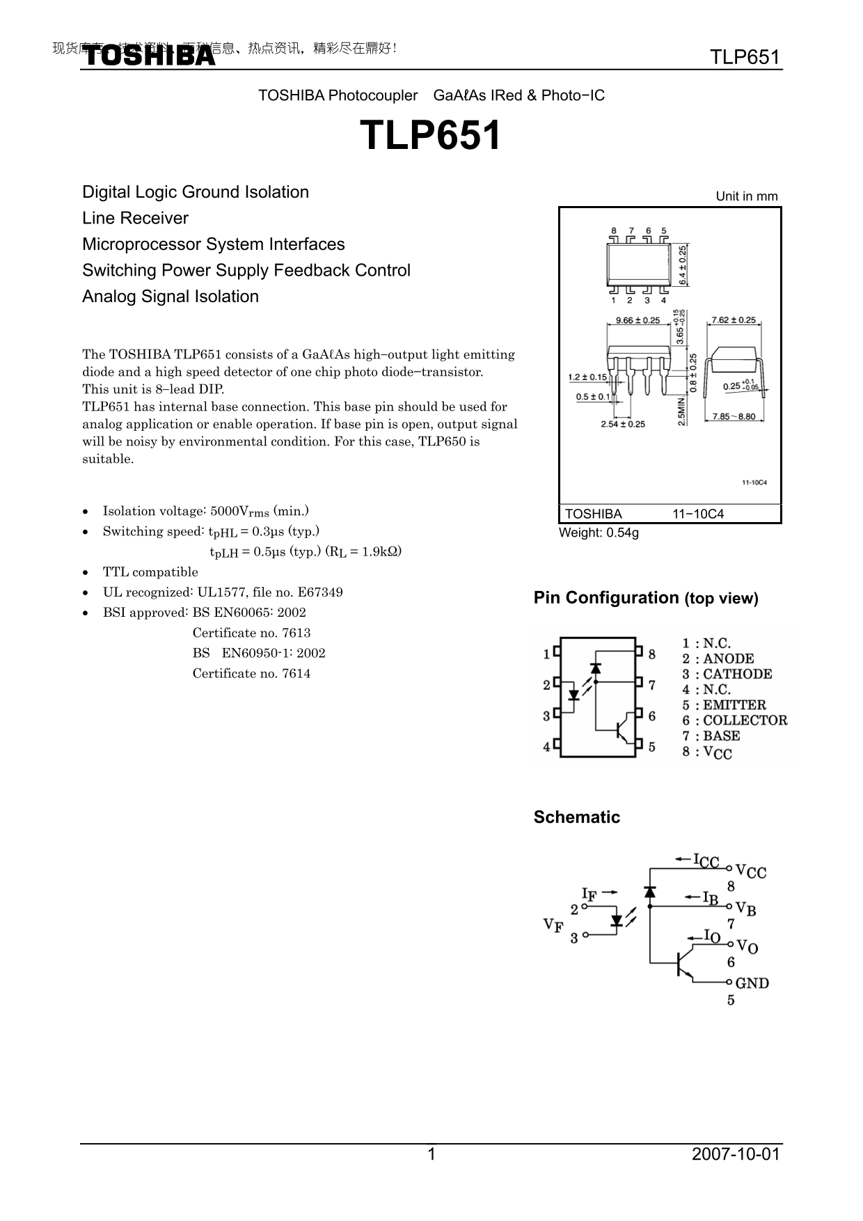
Digital Logic Ground Isolation Unit in mm Line Receiver Microprocessor System Interfaces Switching Power Supply Feedback Control Analog Signal Isolation
The TOSHIBA TLP651 consists of a Ga AℓAs high−output light emitting diode and a high speed detector of one chip photo diode−transistor. This unit is 8−lead DIP. TLP651 has internal base connection. This base pin should be used for analog application or enable operation. If base pin is open, output signal will be noisy by environmental condition. For this case, TLP650 is suitable.
• Isolation voltage: 5000Vrms (min.) TOSHIBA 11−10C4 • Switching speed: tp HL = 0.3μs (typ.) Weight: 0.54g
tp LH = 0.5μs (typ.) (RL = 1.9kΩ)
• TTL compatible • UL recognized: UL1577, file no. E67349
Pin Configuration (top view)
• BSI approved: BS EN60065: 2002
Certificate no. 7613 BS EN60950-1: 2002 Certificate no. 7614
Schematic
Page Summary Contents For Toshiba Photocoupler GaAℓAs IRed & Photo−IC TLP651 Specifications (1)(1) Owner's Manual & User Guide
Manual Details
| Brand | Toshiba |
|---|---|
| Pages | 7 |
| File Size | 488.93 KB |
| Published | July 22, 2026 |
Enter the captcha to get the download link:

Frequently Asked Questions
What is the minimum isolation voltage provided by this component?
The unit provides a minimum isolation voltage of 5000V rms.
Is the TLP651 suitable for medical or aviation equipment?
No, it is not intended for usage in life-critical systems like medical instruments or aircraft electronics (Unintended Usage).
What should be done if the base pin is left open during operation?
If the base pin is open, the output signal may receive noise from environmental conditions.
What is the standard operating temperature range for this component?
The specified operating temperature range for TLP651 is -55 to 100 °C.