Toshiba TOSHIBA Photocoupler GaAℓAs Ired & Photo−IC TLP112A Data Manual
Summary
The TLP112A is a high-performance mini flat optocoupler designed for surface mount applications requiring robust signal isolation. Featuring up to 2500Vrms isolation voltage, this coupler provides reliable digital logic separation essential for feedback control and power supply management in general electronics. This comprehensive manual details the product's electrical characteristics, switching times (t=0.8µs), and maximum ratings, guiding engineers through its integration into various systems like industrial controls and measuring equipment.
Page 1 Text Content
查询TLP112A供应商
TLP112A
TOSHIBA Photocoupler Ga AℓAs Ired & Photo−IC
TLP112A
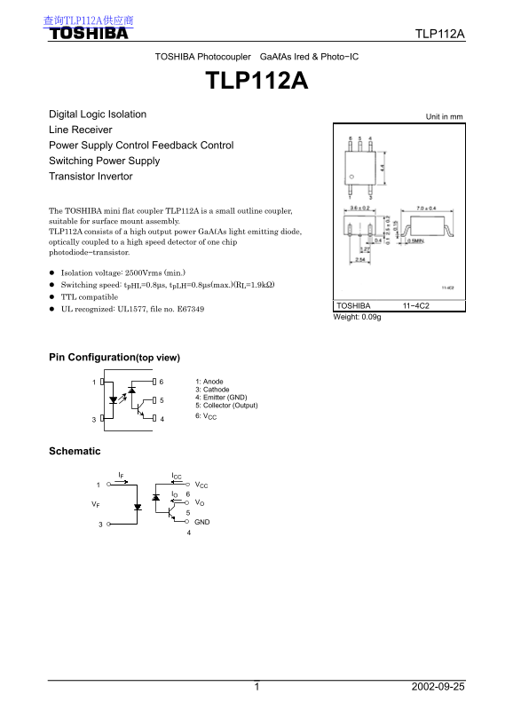
Digital Logic Isolation Unit in mm Line Receiver Power Supply Control Feedback Control Switching Power Supply Transistor Invertor
The TOSHIBA mini flat coupler TLP112A is a small outline coupler, suitable for surface mount assembly. TLP112A consists of a high output power Ga AℓAs light emitting diode, optically coupled to a high speed detector of one chip photodiode−transistor.
Isolation voltage: 2500Vrms (min.) Switching speed: tp HL=0.8µs, tp LH=0.8µs(max.)(RL=1.9kΩ) TTL compatible
TOSHIBA 11−4C2
UL recognized: UL1577, file no. E67349
Weight: 0.09g
Pin Configuration(top view)
1: Anode 3: Cathode 4: Emitter (GND) 5: Collector (Output) 6: VCC
Schematic
IF ICC
VCC IO 6 VO
Page Summary Contents For Toshiba TOSHIBA Photocoupler GaAℓAs Ired & Photo−IC TLP112A Data Manual
Manual Details
| Brand | Toshiba |
|---|---|
| Pages | 7 |
| File Size | 157.62 KB |
| Published | June 04, 2026 |
Enter the captcha to get the download link:

Frequently Asked Questions
What logic level compatibility does the TLP112A offer?
The module is TTL compatible, supporting an operational supply voltage range from 0.5V to 15V.
How fast does the coupler switch states?
Both the high-to-low (t_PLH) and low-to-high (t_PHL) propagation delay times are rated at a maximum of 0.8 µs.
Is this device suitable for critical life support or medical applications?
No, it is not warranted for equipment requiring exceptionally high reliability, such as atomic energy control instruments or medical devices.