Page 1
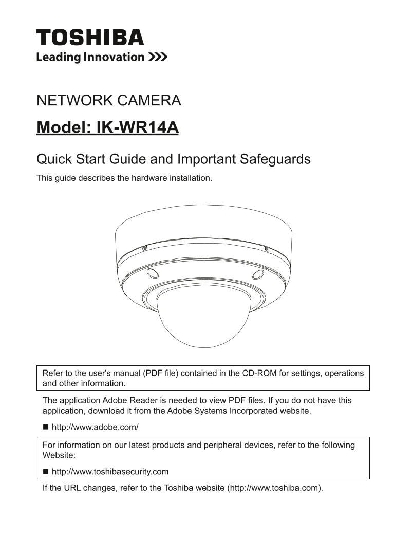
NETWORK CAMERA Model: IK-WR14A Quick Start Guide and Important Safeguards This guide describes the hardware installation. Refer to the user's manual (PDF file) contained in the CD-ROM for settings, op...
Page 2
Introduction FCC (USA)-INFORMATION NOTE: This equipment has been tested and found to comply with the limits for a Class A digital device, pursuant to Part 15 of the FCC Rules. These limits are designe...
Page 3
Thank you for purchasing the IK-WR14A Network Camera. Before using the camera, read this quick start guide carefully to ensure correct usage. After reading this quick start guide, save it for future r...
Page 4
Table of Contents Introduction 2 FCC (USA)-INFORMATION .......................................................................................2 Terms and Trademarks ......................................
Page 5
Important Safeguards 1. Read Instructions Read all the safety and operating instructions before operating the product. 2. Retain Instructions Retain the safety instructions and user's manual for futur...
Page 6
12. Lightning For additional protection on this camera during a lightning storm, or when it is left unattended and unused for long periods of time, unplug it from the wall outlet and disconnect the po...
Page 7
Important Safeguards (Cont.) CAUTION TO REDUCE THE RISK OF ELECTRIC SHOCK. DO NOT REMOVE COVER. NO USER SERVICEABLE PARTS INSIDE. REFER SERVICING TO QUALIFIED SERVICE PERSONNEL. The lightning flash wi...
Page 8
Notes on Use and Installation l Do not aim the camera at the sun Never aim the camera at the sun even with the camera power off. l Do not shoot intense light Intense light such as a spotlight may caus...
Page 9
Setting the Network Camera Environment Items needed for network camera monitoring l Administrator's personal computer The personal computer that allows setting, operating, monitoring and other functio...
Page 10
Package Contents l IK-WR14A l AV Out cable l CD-ROM l Alignment Sticker/Mounting Plate l Warranty Card l Quick Start Guide and Important Safeguards l Waterproof Connector & Bushing l Gasket, Torx ...
Page 11
Physical Description Camera Base Dome Cover Cover screws Side Opening Cover NOTE Replace the side opening cover with the supplied bushing if you want to route cables from the side of camera. The 1/2&q...
Page 12
CAMERA BASE l Front View IR LEDs (SR-LED) Light Sensor Focus Button Lens cover Tilt adjustment Mounting screws screws Status LED l Rear View General I/O Terminal Block Micro SD/ 1. GND SDHC Card 2. Po...
Page 13
Hardware Installation First, use the supplied torx wrench to detach the dome cover from the camera base. Then, follow the steps below to install the camera; either to a ceiling or to a wall. Bottom of...
Page 14
Waterproof Connector Sealing Nut (A) Housing (B) Seals (C) Seal (D) (E) Screw Nut (E) Hex Nut (F) Assembling Steps (F) 1. Disassemble the components of the waterproof connector into parts (A) ~ (E) as...
Page 15
3. You will need an RJ45 crimping tool to attach the Ethernet wires to a connec- tor. When done, connect the cable to the camera’s Ethernet socket . o: white/orange stripe O: orange solid NOTE g: whit...
Page 16
CAUTION l Installation should be done only by qualified personnel and conform to all local codes. l Install this camera on a firm and solid part of the ceiling or wall. If installed improperly or on a...
Page 17
Network Deployment Power over Ethernet (Po E) l When using a Po E-enabled switch The camera is Po E-compliant, allowing transmission of power and data via single LAN cable. See the following illustrat...
Page 18
General Connection (without Po E) 1. Connect the camera to an Ethernet switch via LAN cable. 2. Connect the power cable from a power unit (not supplied) to the appropriate port of the general I/O term...
Page 19
Assigning IP Address 1. Install the "Installation Wizard" under the Software Utility directory from the CD- ROM. 2. The program will analyze your network environment. After your network is a...
Page 20
Retrieving Images 1. Access the Network Camera from the network. 2. Retrieve live video through Internet Explorer®. For more information on camera configuration, please refer to user's manual on the C...
Page 21
Adjusting the Lens Based on the live image retrieved from the camera, adjust the camera lens by performing the following: To adjust the viewing angle 1. Turn the lens module left and right. 2. Loosen ...
Page 22
Dome cover 1. Attach the dome cover to the camera and aligning with the mounting holes. 2. You will find a silica gel bag attached to the dome cover. Remove the supplied silica gel from the aluminum f...
Page 23
Adjusting the Zoom and Focus Access the Network Camera from the browser interface, and click the configuration button onthe main page. Then click the following: Audio and Video Image Zoom and Focus To...
Page 24
TOSHIBA AMERICA INFORMATION SYSTEMS, INC. Surveillance & IP Video Products 9740 Irvine Boulevard, Irvine, CA 92618-1697 Phone Number: (877) 855-1349