Page 1
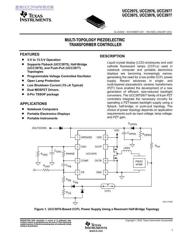
查询UCC2976PW供应商 SLUS499A – NOVEMBER 2001 – REVISED JANUARY 2002 FEATURES DESCRIPTION 3-V to 13.5-V Operation Liquid crystal display (LCD) enclosures and cold Supports Flyback (UCC3975), Half-Bridge cat...
Page 2
SLUS499A – NOVEMBER 2001 – REVISED JANUARY 2002 description (continued) A half-bridge PZT converter, using the UCC3976 is shown in Figure 1. External P- and N-channel MOSFETs are driven out of phase a...
Page 3
SLUS499A – NOVEMBER 2001 – REVISED JANUARY 2002 description (continued) SHUTDOWN COPEN ROPEN OPEN/SD VDD UCC3975 PIEZO XFMR COSCROSC OUTP RANGE COMP OUTN RCNT CFB FB GND RFB DFB CCFLRCS UDG–01098 Figu...
Page 4
SLUS499A – NOVEMBER 2001 – REVISED JANUARY 2002 electrical characteristics VDD = 3 V to 13.5 V, TA = 0°C to 70°C for UCC3975/UCC3976/UCC3977, TA = –40°C to 85°C for the UCC2975/UCC2976/UCC2977, TA = T...
Page 5
SLUS499A – NOVEMBER 2001 – REVISED JANUARY 2002 electrical characteristics VDD = 3 V to 13.5 V, TA = 0°C to 70°C for UCC3975/UCC3976/UCC3977, TA = –40°C to 85°C for the UCC2975/UCC2976/UCC2977, TA = T...
Page 6
SLUS499A – NOVEMBER 2001 – REVISED JANUARY 2002 Terminal Functions TERMINAL UCCx975 I/O DESCRIPTION UCCx976 UCCx977 COMP Output of the error amplifier and control voltage used to set the VCO frequency...
Page 7
SLUS499A – NOVEMBER 2001 – REVISED JANUARY 2002 pin assignments OPEN/SD: This dual-purpose pin provides open lamp protection and a low power shutdown capability for the part. This pin can also be used...
Page 8
SLUS499A – NOVEMBER 2001 – REVISED JANUARY 2002 state diagram A logic state diagram for the UCC397x family of controllers is shown in Figure 5. During power-up the controller transitions from UVLO to ...
Page 9
SLUS499A – NOVEMBER 2001 – REVISED JANUARY 2002 APPLICATION INFORMATION PZT operation Ceramic piezoelectric transformers were first proposed by C.A. Rosen in 1956. Unlike magnetic transformers that re...
Page 10
SLUS499A – NOVEMBER 2001 – REVISED JANUARY 2002 APPLICATION INFORMATION PRIMARY SECONDARY FORCE h = HEIGHTFORCE T = THICKNESS SUPPORTS L = LENGTH MECHANICAL DISPLACEMENT MECHANICAL STRESS UDG–01076 Fi...
Page 11
SLUS499A – NOVEMBER 2001 – REVISED JANUARY 2002 APPLICATION INFORMATION CINPUT COUT RLOAD VIN VOUT UDG–01100 Figure 8. Equivalent Piezoelectric Transformer Circuit Model The component values depend on...
Page 12
IN ai SLUS499A – NOVEMBER 2001 – REVISED JANUARY 2002 APPLICATION INFORMATION lamp characteristics A cold cathode fluorescent lamp has non-linear V-I characteristics as shown in Figure 10. The lamp’s ...
Page 13
SLUS499A – NOVEMBER 2001 – REVISED JANUARY 2002 APPLICATION INFORMATION DC INPUT VOLTAGE RESONANT PIEZOELECTRIC POWER TRANSFORMER STAGE ERROR CCFL AMPLIFIER VOLTAGE VC REF CONTROLLED OSCILLATOR LAMP C...
Page 14
SLUS499A – NOVEMBER 2001 – REVISED JANUARY 2002 APPLICATION INFORMATION Equations 8 and 9 are derived by solving Laplace or differential equations for the RC decay time from 1.7 V to 0.7 V with and wi...
Page 15
SLUS499A – NOVEMBER 2001 – REVISED JANUARY 2002 APPLICATION INFORMATION setting lamp current The lamp current is controlled by adjusting the frequency of the PZT. System frequency and lamp current con...
Page 16
SLUS499A – NOVEMBER 2001 – REVISED JANUARY 2002 APPLICATION INFORMATION matching the PZT to the lamp, input voltage and topology A fundamental challenge in the design of a piezoelectric transformer-ba...
Page 17
SLUS499A – NOVEMBER 2001 – REVISED JANUARY 2002 APPLICATION INFORMATION half-bridge operation and inductor selection In the half-bridge topology, the external inductor and piezoelectric capacitance fo...
Page 18
SLUS499A – NOVEMBER 2001 – REVISED JANUARY 2002 APPLICATION INFORMATION half-bridge operation and inductor selection (continued) Waveforms for the UCC3976 half-bridge circuit operated with a 12-Vdc in...
Page 19
SLUS499A – NOVEMBER 2001 – REVISED JANUARY 2002 APPLICATION INFORMATION push-pull operation and inductor selection For the push-pull circuit, MOSFETs N1 and N2 are driven out of phase with 50% duty cy...
Page 20
SLUS499A – NOVEMBER 2001 – REVISED JANUARY 2002 APPLICATION INFORMATION flyback operation For single layer PZT applications requiring additional gain, a resonant flyback topology can be implemented as...
Page 21
SLUS499A – NOVEMBER 2001 – REVISED JANUARY 2002 ff ic ie cy APPLICATION INFORMATION analog dimming PZT performance High efficiency can be achieved by selecting the best power topology while matching t...
Page 22
SLUS499A – NOVEMBER 2001 – REVISED JANUARY 2002 APPLICATION INFORMATION open lamp shutdown/no-lock operation Due to the high gain characteristics of the piezoelectric transformer, it is important that...
Page 23
SLUS499A – NOVEMBER 2001 – REVISED JANUARY 2002 APPLICATION INFORMATION open lamp shutdown/no-lock operation (continued) Figure 20 shows the startup performance of the UCC397x family based system with...
Page 24
SLUS499A – NOVEMBER 2001 – REVISED JANUARY 2002 APPLICATION INFORMATION open lamp shutdown/no-lock operation (continued) VCOMP VOPEN/SD Figure 21. Start-Up With Insufficient Input Voltage www.ti.com
Page 25
SLUS499A – NOVEMBER 2001 – REVISED JANUARY 2002 APPLICATION INFORMATION burst dimming with the OPEN/SD pin A burst dimming technique can be used with CCFLs when a wide dimming range is required, this ...
Page 26
SLUS499A – NOVEMBER 2001 – REVISED JANUARY 2002 TYPICAL WAVEFORMS VIN = 12 Vdc VLAMP = 600 V f OSC = 125 Hz 10% Duty Cycle ILAMP = 5 m A VOPEN/SD VOPEN/SD VCOMP VLAMP Figure 23. UCC3976 Externally Con...
Page 27
SLUS499A – NOVEMBER 2001 – REVISED JANUARY 2002 TYPICAL WAVEFORMS VIN = 12 Vdc VLAMP = 600 V f OSC = 125 Hz 10% Duty Cycle ILAMP = 5 m A VOPEN/SD VOPEN/SD VCOMP VLAMP Figure 25. UCC3976 Close-Up of Bu...
Page 28
IMPORTANT NOTICE Texas Instruments Incorporated and its subsidiaries (TI) reserve the right to make corrections, modifications, enhancements, improvements, and other changes to its products and servic...